Solar Power and PoE: Designing Off-Grid Networks
Learn how solar power and PoE combine for off-grid cameras and networks, including power paths, PoE compatibility, voltage checks and load planning.
By Maxsol Team

Solar power and Power over Ethernet can work together to run an IP camera, wireless bridge or access point where grid electricity is unavailable. The solar system generates and stores DC energy, while a compatible DC-to-PoE interface converts that energy into the voltage and wiring arrangement required by the network device.
The important limitation is that PoE supplies power and carries Ethernet data, but it does not create the network connection. Solar power and PoE off-grid networking therefore needs two planned paths: an energy path from the panel to the device, and a data path from a router, switch, recorder, radio or other network source.
Trace the solar energy and Ethernet data paths
A typical off-grid PoE installation has two paths that meet at the PoE interface.
The energy path
The power path normally follows this sequence:
- Solar panel: Converts sunlight into DC electrical energy.
- Solar charge controller: Regulates the panel output and manages battery charging.
- Battery: Stores energy so that equipment can continue operating when solar generation is low or unavailable.
- DC protection and cabling: Connects the battery-side output to the load through correctly selected protection, conductors and connectors.
- DC-to-PoE interface: Converts or regulates the battery voltage and applies power to the required Ethernet conductors.
- Powered network device: Uses the delivered power to operate the camera, access point, bridge or other endpoint.
For example, the Maxsol CS12060 solar power system documents a 120W monocrystalline panel, a 12.8V 60Ah 768Wh LiFePO4 battery, an MPPT controller and three DC12V outputs. RS485 is optional. These specifications describe the system components, but they do not by themselves establish runtime for a particular PoE device.
The controller’s current datasheet and supplied configuration should be checked for its PV voltage, PV current and panel-power limits. Battery charging temperature limits, protection behaviour and load-output settings also need confirmation before installation.
The data path
Ethernet data comes from a separate network source, such as:
- a router or network switch;
- a network video recorder;
- a wireless point-to-point or point-to-multipoint link;
- a cellular router;
- a fibre or copper network hand-off; or
- another upstream Ethernet device.
The Ethernet connection enters the PoE injector or converter, where power is added to the cable. A single Ethernet cable then carries both data and power to the endpoint.
This distinction prevents a common design error: connecting a solar battery and PoE converter to a camera does not provide remote connectivity on its own. The installation still needs an upstream network, local recorder or wireless backhaul appropriate to the project.
Separate charging, storage and PoE functions
A dependable design treats solar charging, energy storage and PoE delivery as separate functions. Combining them mentally into one “solar PoE box” can hide compatibility problems.
| Function | Main component | What it must do | What to verify |
|---|---|---|---|
| Generate energy | PV module | Produce DC power from sunlight | Electrical ratings and controller compatibility |
| Control charging | Solar charge controller | Regulate charging and protect the battery system | PV limits, battery profile, load settings and temperature requirements |
| Store energy | Battery | Supply energy outside useful solar periods | Nominal voltage, operating range, protection limits and usable energy |
| Convert power | DC-to-PoE interface | Convert battery-side DC to the endpoint’s required PoE supply | Input range, output voltage, load limit, polarity, pinout and protocol |
| Carry data | Ethernet interface and cabling | Connect the endpoint to its network source | Data rate, cable quality, distance, termination and surge exposure |
| Use power | Camera, radio or access point | Operate within the available electrical budget | PoE type, voltage range, peak demand and environmental rating |
This separation also makes fault-finding easier. If a camera disconnects overnight, the cause might be depleted storage, a battery protection cut-off, voltage drop, converter overload or a network fault. It is not necessarily a solar-panel problem.
Protection should also be considered at component boundaries. Appropriate fusing or DC circuit protection, cable sizing, earthing and surge protection depend on the installation, equipment instructions and site conditions. Outdoor Ethernet runs can create a separate surge path even when the power source is fully off-grid.
Distinguish passive PoE from IEEE negotiation
“PoE” does not always describe the same electrical behaviour. The main distinction is between passive voltage injection and negotiated IEEE PoE.
Passive PoE
A passive injector places a specified voltage onto specified Ethernet conductors whenever it is powered. It does not necessarily check whether the connected device is compatible before energising the cable.
A passive system can work when all of the following match:
- required device voltage;
- voltage tolerance;
- connector or Ethernet pinout;
- polarity;
- current demand;
- cable arrangement; and
- data requirements.
A mismatch can prevent operation or damage equipment. A selectable or adjustable voltage control does not make an injector IEEE-compliant and does not automatically make it safe for every PoE device.
Negotiated IEEE PoE
IEEE PoE equipment generally uses detection and classification procedures before applying normal operating power. Common standards include IEEE 802.3af, 802.3at and 802.3bt, although support for a standard must be verified on both the power-sourcing and powered-device sides.
The practical difference is significant:
| Question | Passive PoE | Negotiated IEEE PoE |
|---|---|---|
| Is power normally applied without powered-device detection? | Often yes | Normally no |
| Does an adjustable voltage prove compatibility? | No | No |
| Must pinout and polarity be checked? | Yes | Yes, together with standard and implementation |
| Can the device’s “PoE” label alone confirm a match? | No | No |
| Is protocol confirmation required? | Yes | Yes |
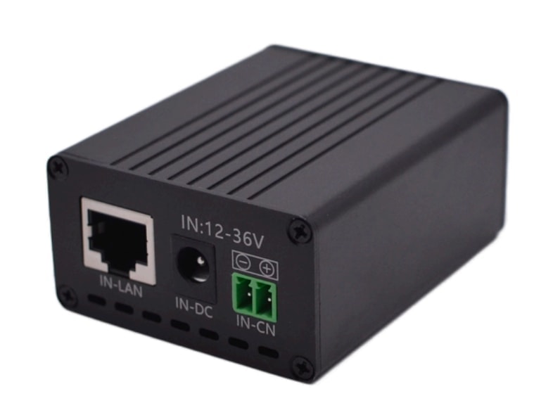
The Maxsol POE24V DC-to-PoE converter accepts 12–36V DC and provides an adjustable 12–57V PoE output, Gigabit Ethernet and an LCD voltage display. Its documented continuous load limit for 12V-to-48V conversion is no more than 30W.
Those details do not establish IEEE powered-device detection or negotiation. Before connecting a device, verify the required output voltage, polarity, pinout and PoE protocol. The solar system and converter linked in this article are selection examples, not a tested or guaranteed compatible bundle.
Match battery and converter operating voltages
Voltage matching must be based on operating ranges, not only the nominal number printed on the battery.
A 12.8V battery does not remain at exactly 12.8V throughout charging and discharging. Its terminal voltage changes with state of charge, current, temperature, charging conditions and protection behaviour. The DC-to-PoE interface must tolerate the complete voltage range it will experience.
Check these five values:
- Battery or load-output minimum voltage: The converter must continue operating above the system’s expected low-voltage cut-off.
- Maximum charging voltage: The converter input must tolerate the highest voltage permitted by the battery and controller.
- Required PoE output voltage: The setting must match the powered device’s documented input requirement.
- Continuous current and power: The converter, battery-side output and cabling must all support the load.
- Voltage drop: Long or undersized DC and Ethernet cables can reduce the voltage reaching the device.
Do not assume that a converter with a 48V setting is compatible with every device described as “48V PoE”. Confirm whether the endpoint expects passive power or IEEE negotiation, which pairs carry power, its permitted voltage range and its maximum demand.
Connector compatibility matters as well. A physically fitting connector does not prove matching polarity or voltage. Confirm centre-positive or centre-negative arrangements where barrel connectors are used, and avoid relying on cable colour alone.
Budget continuous and startup demand
An off-grid system must support more than the endpoint’s headline wattage. The battery may also be powering a router, wireless radio, switch, recorder, heater, infrared illuminator or other accessory.
The total demand should account for:
- the powered device’s normal operating load;
- peak or startup demand;
- night-time infrared operation on cameras;
- radios transmitting at higher power;
- converter losses;
- charge-controller and protection-system consumption;
- routers, switches and backhaul equipment;
- cable losses; and
- any environmental controls inside the enclosure.
Hypothetical load example
The following is a hypothetical design assumption, not measured product performance or a sizing recommendation.
Suppose a camera consumes 10W during daytime operation and reaches 14W when its infrared illumination is active. If the assumed DC-to-PoE conversion efficiency at the relevant operating point is 85%, the battery-side demand during infrared operation would be approximately:
14W ÷ 0.85 = 16.5W
If an upstream wireless radio draws another assumed 6W from the same battery system, the combined battery-side load would already be about 22.5W before allowing for controller consumption, cable loss or startup peaks.
This example shows why the camera wattage alone is not enough. It also illustrates why a published maximum conversion efficiency should not be used as the guaranteed design efficiency. The POE24V documentation lists conversion efficiency of up to 94%; “up to” is a maximum, not a value assured across every input voltage, output setting and load.
Likewise, a 768Wh nominal battery does not deliver 768Wh of usable energy to the endpoint. Battery protection limits, state of charge, temperature, conversion losses, cable losses, ageing and the selected depth of discharge all affect delivered energy. Nominal watt-hours cannot establish universal autonomy, battery service life or guaranteed 24/7 operation.
For a detailed device-side calculation, use a structured PoE power budget for security cameras. Solar-array and storage selection should then be handled separately through an off-grid solar sizing process for CCTV rather than treating panel wattage as equivalent to continuous load capacity.
Do not overlook startup and intermittent peaks
Some network devices draw more power when starting, transmitting, switching on infrared LEDs or activating heaters. A system may appear adequate based on average consumption but reset when a short peak causes:
- converter current limiting;
- excessive voltage drop;
- battery protection activation;
- charge-controller load-output shutdown; or
- the PoE device’s voltage falling below its operating threshold.
Obtain maximum input-power figures from the endpoint manufacturer where possible. If only typical consumption is published, request or measure peak demand under the intended operating modes rather than assuming that typical and maximum power are equal.
Review a compatible architecture checklist
Before powering an existing PoE camera or other network endpoint from solar energy, work through the complete architecture rather than checking components individually.
Powered-device compatibility
- What PoE standard or passive voltage does the device require?
- Is IEEE 802.3af, 802.3at or 802.3bt support explicitly documented?
- If it uses passive PoE, what are the required voltage, polarity and pinout?
- What are its typical, maximum and startup power demands?
- Does night mode, infrared illumination, heating or radio transmission increase consumption?
- Is the endpoint intended for the installation’s temperature, moisture and dust exposure?
DC-to-PoE interface
- Does its input range cover the battery’s entire operating range?
- Can its output be set to the device’s required voltage?
- Does it use the correct polarity and powered pairs?
- Does it provide the required IEEE negotiation, or is it passive?
- Is its continuous load rating sufficient at the actual input and output voltages?
- Can it support startup demand without its output collapsing?
- Does its Ethernet interface support the required network speed?
Solar charging and storage
- Is the panel electrically compatible with the charge controller?
- Are the controller’s PV voltage, current and power limits confirmed?
- Is the correct battery charging profile configured?
- Are battery charging-temperature restrictions addressed?
- Is the controller load output suitable for the converter’s continuous and peak current?
- Has usable storage been calculated after realistic system losses?
- Is there enough reserve for the required low-solar period without assuming guaranteed sunshine?
Data and communications
- Where does the Ethernet data originate?
- Does the PoE interface pass the required data rate?
- Is a router, recorder or wireless backhaul also powered at the site?
- If the backhaul fails, does the camera have local recording or another required fallback?
- Are cable length, termination quality and voltage drop acceptable?
- Is outdoor surge exposure addressed on both power and data paths?
Installation and maintenance
- Are DC conductors sized for current and distance?
- Are connectors keyed, labelled and protected against accidental reversal?
- Are suitable fuses or protective devices installed close to energy sources?
- Is the enclosure appropriate for heat, moisture, dust and cable entry?
- Can installers safely isolate the panel, battery and loads independently?
- Are voltage settings recorded so that they are not changed accidentally?
- Can battery state, controller status and network connectivity be inspected during maintenance?
Common mistakes to avoid
Several mistakes recur in solar-powered PoE projects:
- Connecting a solar panel directly to a PoE converter. A panel’s output varies and normally requires a charge controller and battery or another properly designed regulated energy stage.
- Assuming every “PoE camera” uses the same voltage and protocol. Passive PoE and IEEE PoE are not interchangeable by default.
- Treating adjustable output as automatic compatibility. Voltage is only one requirement; detection, polarity and pinout still matter.
- Forgetting the data source. A powered camera is not necessarily a connected camera.
- Sizing from average load alone. Startup, infrared, radio-transmission and other operating peaks can cause resets.
- Using nominal battery watt-hours as delivered energy. The endpoint receives less after operating limits and system losses.
- Ignoring the other network equipment. Routers, bridges and switches may consume as much energy as the endpoint.
- Designing at a converter’s absolute limit. Operating conditions and peak demand need appropriate engineering allowance.
- Assuming two components are compatible because their nominal voltages look similar. Full operating ranges and interface details must be checked.
Can an existing PoE camera be converted to solar power?
Usually, an existing PoE camera can be powered from an off-grid solar system if its electrical and network requirements are fully understood. The camera itself generally does not need to know that its energy originates from solar panels.
The safest process is:
- Record the camera’s PoE standard or passive-power requirements.
- Confirm its voltage range, pinout, polarity and maximum power.
- Identify every other device that must operate at the remote site.
- Select a battery-side DC-to-PoE interface with the correct input range and output behaviour.
- Plan the data source and backhaul separately.
- Calculate continuous and peak load before sizing solar generation and storage.
- Test all intended operating modes, including night operation and network transmission.
- Document voltage settings, protection and wiring before deployment.
If any PoE detail is missing from the camera documentation, do not rely on trial and error. Confirm it with the device supplier or use appropriate test equipment before applying power.
Practical next step
Start with the endpoint: document its port count, load, startup demand, distance, PoE protocol, voltage, environmental conditions and network-management needs. Then compare those requirements with the current datasheets and supplied configurations of the linked Maxsol solar system and DC-to-PoE converter, including controller limits, battery temperature requirements, input range, output setting and continuous-load ceiling. This confirms whether the components suit the architecture without assuming that they form a pre-validated bundle.