Size an Off-Grid Solar Power System for CCTV Cameras
Calculate the solar panel and battery capacity for off-grid CCTV in South Africa, allowing for site load, sunlight, losses and backup time.
By Maxsol Team

An off grid solar power system for CCTV cameras must be sized from the site’s actual daily energy use—not simply by the number of cameras. Add the power draw of every camera, PoE switch, wireless bridge, recorder and accessory; convert this to watt-hours per day; then allow for solar resource, conversion losses and the number of low-sun days the system must ride through.
For South African installations, panel orientation, seasonal sunlight, shading, heat and the site’s overnight load can materially affect the result. Start with conservative inputs, then validate the design against measured equipment consumption and the proposed installation location.
Inventory the full site load
List every device that will draw energy from the solar system. A camera’s published maximum consumption can be useful for planning, but it is best to measure the real installed load where possible. Fixed cameras may have a relatively steady draw, while PTZ movement, infrared illumination, heaters, wireless transmission and PoE demand can change consumption significantly.
Include these items where applicable:
- IP cameras, analogue cameras and camera converters
- PoE switch or PoE injector
- Wireless CPE, point-to-point bridge or access point
- NVR, edge recorder, router or cellular gateway
- Network switch, media converter and fibre equipment
- DC-to-DC converters and any AC inverter
- Security lights, sirens, gate equipment or sensors sharing the supply
- Controller standby consumption and battery-management overhead
Do not assume that a device marked “12 V” is directly compatible with a solar system’s output. Confirm its input voltage range, connector, polarity, peak current and whether it needs regulated power. For PoE equipment, establish the required PoE standard, voltage, port power and total PoE budget. A camera’s PoE requirement is not the same as its average wattage.
Create a load schedule, not just a wattage list
Daily energy depends on operating hours. Most surveillance cameras and network devices run 24 hours a day, but a light or PTZ function may only operate for a portion of the day.
Use this basic worksheet:
| Equipment | Quantity | Operating power (W) | Hours per day | Daily energy (Wh) |
|---|---|---|---|---|
| Camera | 4 | 6 | 24 | 576 |
| PoE switch | 1 | 12 | 24 | 288 |
| Wireless bridge | 1 | 8 | 24 | 192 |
| Total | 1,056 Wh/day |
The figures above are an example only. They are not a recommended load or a runtime estimate for any solar system.
Where equipment has a high start-up or temporary peak load, record both:
- Continuous load, used for daily-energy calculations.
- Peak load, used to check the output ports, converters, protection devices and any inverter.
A system can have adequate battery watt-hours but still fail if a power output, cable or converter cannot support a momentary peak.
Convert load into daily energy
Calculate each device’s daily energy with:
Daily energy (Wh) = power (W) × operating time (hours/day)
Then add all rows together. For a CCTV site that operates continuously, total power can be multiplied by 24:
Daily energy (Wh/day) = continuous site load (W) × 24
For example, a site with a measured continuous load of 25 W requires:
25 W × 24 h = 600 Wh/day
This is the load energy before allowing for power-system losses. It is usually safer to add a documented or planned allowance for growth, especially where spare PoE ports, an additional camera, a radio link or stronger night illumination may be introduced later.
A practical planning calculation is:
Design daily energy = measured daily energy × expansion allowance
An allowance of 10% to 25% may be appropriate when expansion is genuinely expected. It should not replace proper measurement or be used to hide unknown loads.
Avoid mixing watts, watt-hours and amp-hours
These three figures answer different questions:
- Watts (W): instantaneous power draw.
- Watt-hours (Wh): energy used or stored over time.
- Amp-hours (Ah): battery charge capacity at a stated voltage.
For comparison, battery energy is approximately:
Wh = battery voltage × Ah
A 12.8 V, 30 Ah battery is therefore nominally 384 Wh. However, nominal battery capacity is not automatically the energy available to every connected device. Battery protection settings, permitted discharge depth, cable losses, voltage conversion and the load profile all reduce usable delivered energy.
Account for solar resource and losses
The PV panel must replace the energy used by the CCTV equipment and recover the battery after overnight operation. For solar sizing, use the site’s peak sun hours (PSH) for the least favourable operating period, rather than relying on a summer average.
South Africa has strong solar potential in many areas, but a site can still underperform due to winter conditions, coastal cloud, local terrain, dust, shading or poor panel orientation. Use location-specific solar-resource data in the final design and inspect the mounting position throughout the day.
A simplified PV-array calculation is:
Required panel rating (W) = design daily energy (Wh) ÷ (peak sun hours × system efficiency factor)
The system efficiency factor accounts for real-world losses such as:
- Panel temperature and soiling
- MPPT or charge-controller conversion
- Battery charging and discharging losses
- DC cable voltage drop
- DC-to-DC conversion or inverter losses
- Equipment consumption while charging
For early planning, use a conservative factor rather than assuming the panel delivers its nameplate rating for every sun hour. The correct factor depends on the architecture, equipment and conditions.
Example panel calculation
Assume a CCTV site has a design energy requirement of 600 Wh/day, a conservative solar-resource input of 4 peak sun hours and an overall efficiency factor of 0.70:
600 Wh ÷ (4 × 0.70) = 214 W
This example points to a PV capacity of at least about 214 W before further site-specific design decisions. It does not mean a 200 W system will reliably operate that load at every location or in every season. The load, usable battery energy, panel angle, weather pattern and recovery requirement must all be assessed together.
Design for the difficult days
A solar system that works on a clear day may not have enough generation to recover after several cloudy days. Review:
- The lowest-sun seasonal period for the site
- Shade from poles, trees, buildings, fences or nearby equipment
- Soiling from dust, birds or industrial environments
- Panel tilt, orientation and secure mounting
- Ambient temperature and enclosure heat
- Cable route and conductor size
- Whether the system must recharge fully after one or more low-sun days
Do not place a panel where it is unshaded only at midday. Morning and afternoon shade can reduce useful daily generation considerably.
Choose battery autonomy
Battery autonomy is the number of days the CCTV load can continue without useful solar charging. The right target depends on security risk, site access, expected weather, maintenance strategy and whether a backup charging source exists.
Calculate nominal battery energy required as:
Required nominal battery energy (Wh) = design daily energy × autonomy days ÷ allowed usable battery fraction
The allowed usable battery fraction is a design choice, not a universal fixed number. It should account for the battery-management system’s cut-off behaviour, desired battery life, low-temperature performance where relevant and energy lost in conversion.
For example, if a site needs 600 Wh/day, requires two days of autonomy and is designed around 80% usable battery energy:
600 Wh × 2 ÷ 0.80 = 1,500 Wh nominal battery capacity
This indicates that a nominal 1,500 Wh battery bank would be the starting point for further design checks. It does not account for an inverter or other conversion losses unless these were already included in the design daily energy.
Overnight runtime is only one check
For a 24-hour CCTV site, the battery must normally cover the night and periods of reduced generation. A useful first check is:
Estimated battery runtime (hours) = usable battery energy (Wh) ÷ average load (W)
If a 384 Wh nominal battery had 80% usable energy available to a 16 W load:
(384 Wh × 0.80) ÷ 16 W = 19.2 hours
That is a planning illustration, not a product runtime claim. In practice, output conversion, cable losses, solar charging conditions and the true camera load will change the result. It also shows why a battery sized only for one average night may offer limited resilience after poor weather.
Compare documented 192 Wh to 1280 Wh systems
The following Maxsol solar systems are documented capacity examples. They should be compared against your calculated daily load and autonomy target, not selected solely because the panel rating or battery figure appears close to the camera count.
| System example | Documented panel configuration | Documented battery capacity | Selection considerations |
|---|---|---|---|
| CS3015 | 30 W monocrystalline panel | 12.8 V 15 Ah, 192 Wh | Small documented capacity; confirm all connected DC loads and required overnight reserve. |
| CS6030 | 60 W panel | 12.8 V 30 Ah, 384 Wh | Compare against daily energy, expected solar input and recovery after overnight use. |
| CS12060 | 120 W panel | 12.8 V 60 Ah, 768 Wh | Consider where the calculated load, autonomy requirement or planned expansion exceeds smaller options. |
| CS200100 | 200 W system configuration | 12.8 V 100 Ah, 1280 Wh | Assess for larger energy requirements, while checking actual solar resource and output compatibility. |
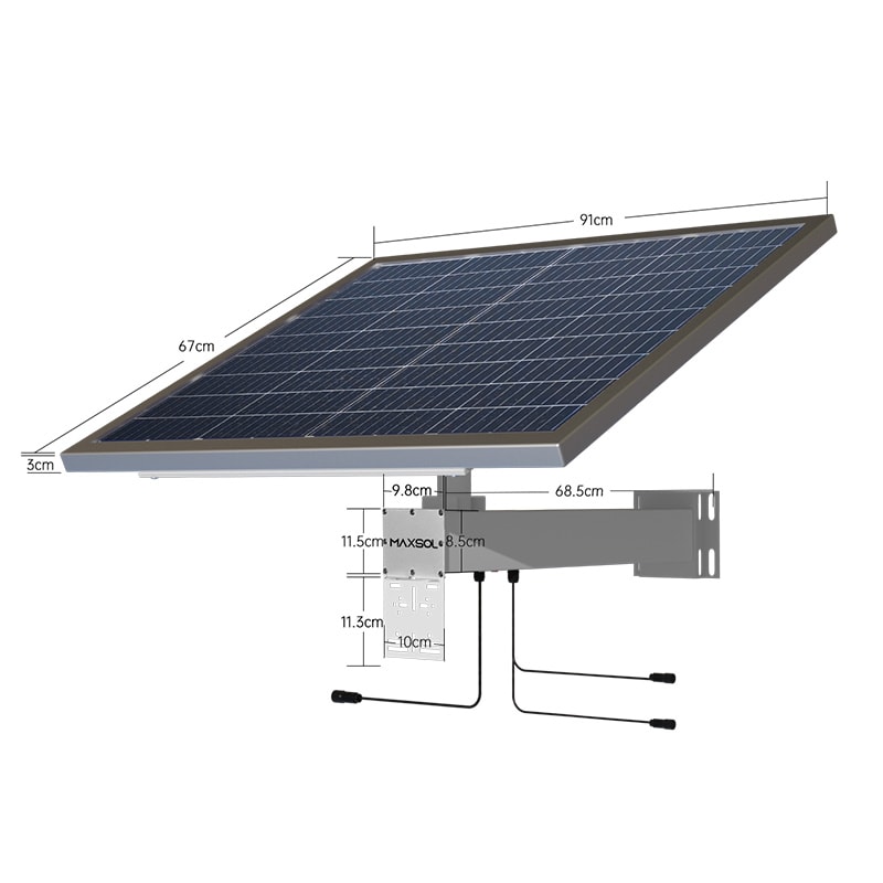
The CS3015 30 W solar system with 192 Wh LiFePO4 battery combines a 30 W monocrystalline panel, 12.8 V 15 Ah 192 Wh LiFePO4 battery, MPPT controller and three DC 12 V output ports. Those three output ports do not by themselves define the number of cameras supported: the combined load, power requirements and output compatibility remain decisive.
The CS6030 60 W solar system with 384 Wh battery documents a 60 W panel with a 12.8 V 30 Ah, 384 Wh battery. It may be a useful comparison point for a modest calculated load, but runtime and recharge performance still depend on site conditions.
The CS12060 120 W solar system with 768 Wh battery documents a 120 W panel and 12.8 V 60 Ah, 768 Wh battery. Compare its nominal stored energy with the usable energy needed for the selected autonomy period, then check whether 120 W of solar generation is sufficient during the least favourable season.
The CS200100 200 W solar system with 1280 Wh battery documents a 200 W system configuration and 12.8 V 100 Ah, 1280 Wh battery. It provides a larger documented energy basis for comparison, but it is not a guarantee of runtime for an unspecified CCTV load or location.
Validate before purchase
A sound calculation should be followed by an engineering and installation check. This prevents common problems such as a battery that covers one night but cannot recover during the day, or a solar output that is electrically unsuitable for a PoE network.
Use this pre-purchase checklist:
- Measure the complete load. Record typical and maximum watts for cameras, network equipment and accessories. Test cameras with infrared illumination active and PTZ movement where applicable.
- Confirm 24-hour energy. Multiply each device’s wattage by actual daily operating hours and add the results.
- Check the power path. Identify every DC converter, PoE injector, switch or inverter between the battery and the device. Include its losses in the energy budget.
- Define autonomy. State how many days of limited solar generation the site must tolerate before CCTV outage becomes unacceptable.
- Use conservative solar assumptions. Model the lower-sun season and inspect for year-round shade, not just the conditions on installation day.
- Check output compatibility. Verify DC voltage, current, connectors, polarity, PoE requirements, port count and total output capacity.
- Review physical installation. Plan safe panel mounting, suitable cable lengths and conductor sizes, protected cable entry, weather exposure and access for cleaning.
- Allow for expansion. Account for spare camera capacity, radio links, recording equipment or future loads before fixing the battery and panel size.
- Commission and monitor. After installation, measure daytime generation, battery state and actual load over representative weather conditions.
Common sizing mistakes
The most frequent error is sizing from the camera quantity alone. Four low-power fixed cameras can have a very different energy requirement from four infrared or PTZ cameras served by a PoE switch and wireless backhaul.
Other mistakes include using panel wattage as daily energy, omitting a network switch from the load table, assuming all nominal battery capacity is usable, overlooking winter shading, and adding an AC inverter where a direct DC design could avoid unnecessary conversion losses.
A further risk is placing cameras at a distant pole while locating the battery system far away. Long DC cable runs can create voltage drop. The cable length, conductor size, source voltage and load current should therefore be designed together.
FAQ
How many CCTV cameras can a 192 Wh solar system run?
There is no fixed camera number. Divide the usable battery energy by the measured total load to estimate runtime, then check whether the panel can replace that energy under the site’s least favourable solar conditions. Camera type, PoE equipment, infrared operation and network gear can matter as much as the camera count.
Is a larger battery enough if the panel is too small?
No. A larger battery can extend backup time, but it cannot create energy. If the panel cannot replace daily consumption and recharge the battery after low-sun periods, the battery will gradually run down.
Should a solar CCTV system use DC or AC power?
Where compatible equipment is available, a DC power path can reduce conversion stages. However, the correct choice depends on the camera, PoE network, cable distance, required voltage and output interfaces. Do not select an architecture without verifying electrical compatibility for every device.
How much extra capacity should be allowed for expansion?
Base the allowance on a defined future load, such as one additional camera and its share of PoE or wireless equipment. A percentage contingency can support early planning, but it should be replaced with watts and operating hours before final selection.
Compare the linked Maxsol models against your required port count, measured load, cable distance, power requirements, site environment and management needs before specifying an off-grid CCTV power system.