PoE Power Budget Calculator for Security Cameras
Calculate a safe PoE budget for security cameras using port limits, simultaneous demand and headroom. Compare 120W, 300W and 400W options.
By Maxsol Team

To calculate a PoE power budget for security cameras, add the power required by every device that may operate at the same time, then check that each device fits its individual PoE port limit and that the combined demand remains below the switch’s total PoE budget. Finally, leave practical headroom for peak functions, cable-related allocation and future changes.
A reliable PoE power budget calculator for cameras does not start with the switch’s port count. It starts with the camera manufacturer’s stated maximum input power, including features such as IR illumination, heaters, blowers, pan-tilt-zoom movement and auxiliary devices. A switch with enough ports can still be underpowered if its total budget or per-port capability is too low.
Collect each device power requirement
Create a device schedule before selecting the switch. Record every powered device, not only fixed cameras. A surveillance network may also include PTZ cameras, door stations, wireless bridges, intercoms, access points or other PoE-powered equipment connected to the same switch.
Use the device manufacturer’s documented maximum power requirement for your calculation. Avoid estimating consumption from camera type alone: two cameras with similar resolution can have very different peak demand.
Your schedule should include:
| Device or load | Quantity | Maximum power per device | Simultaneous? | Power class or requirement | Notes |
|---|---|---|---|---|---|
| Fixed camera | Yes/No | Include night-mode requirement | |||
| PTZ camera | Yes/No | Include movement and IR/heater load | |||
| Outdoor camera with heater | Yes/No | Confirm cold-start and heater demand | |||
| Wireless bridge or AP | Yes/No | Check its stated PoE input | |||
| Other PoE device | Yes/No | Record exact model requirement |
For each item, use the value specified at the power sourcing equipment (PSE) side where available. If a data sheet provides only device input power, consult the manufacturer’s installation guidance to establish the required PoE standard and switch-side allocation.
Why ordinary running power is not enough
A camera may draw less power during the day than at night. IR LEDs, motor movement, heating and startup can increase demand. If the calculation is based only on a typical daytime figure, the design may appear sound until all cameras change state together.
For a resilient design, use one of these approaches:
- Maximum documented demand: The simplest and most conservative method.
- Defined simultaneous-load scenario: Appropriate where documented control logic prevents certain loads operating together.
- Measured demand plus validated allowance: Useful for an existing, controlled installation, but should not replace manufacturer limits in a new specification.
Do not assume that a camera’s advertised PoE standard tells the full story. Confirm both its maximum wattage and the port standard it requires.
Separate per-port limits from total budget
Every PoE design has two separate tests:
- Can an individual port supply the connected device?
- Can the switch supply all connected devices together?
Passing one test does not guarantee that the other will pass.
Per-port power limit
A port has a maximum power level and may support only particular IEEE PoE standards. A device requiring more power than a port can provide may fail to start, lose optional functions or cycle on and off. This remains true even when most of the switch’s total power budget is unused.
For example, a switch may have a large shared budget, but ports designed for IEEE 802.3af/at devices may be limited to 30W per port. A higher-demand device may require a port with IEEE 802.3bt support instead.
Check:
- The PoE standard required by the device: IEEE 802.3af, 802.3at or IEEE 802.3bt.
- The maximum power available from the specific switch port.
- Whether certain ports have different capabilities from the rest.
- The device’s required power at the far end of the cable.
- Any manufacturer requirements for cable category, length or installation conditions.
Total PoE budget
The total PoE budget is the maximum power the switch can allocate across its PoE ports. It is not the same thing as the number of physical ports, and it should not be confused with an internal power supply figure unless the manufacturer explicitly states the usable PoE budget.
For instance, a 16-port switch with 30W available on every port would have a theoretical per-port total of 480W. That does not mean the switch has a 480W shared PoE budget. Always use the documented total budget for the model.
Cable length and losses
Ethernet cable resistance causes voltage drop and power loss. PoE standards and compliant equipment account for this within their intended operating limits, but long runs, poor-quality cable, damaged conductors and unsuitable terminations can reduce the power available at the device.
A sound power budget cannot compensate for incorrect cabling. Confirm:
- Cable type and conductor quality;
- Run length against the device and switch documentation;
- Correct termination and continuity;
- Environmental suitability for external cabling; and
- Whether a high-power device has additional cable requirements.
Add simultaneous load and headroom
Once each device’s maximum demand is known, calculate the simultaneous load:
Simultaneous PoE load = sum of maximum power for all devices expected to operate together
Then add design headroom:
Required switch PoE budget = simultaneous PoE load × (1 + headroom percentage)
For many camera installations, a headroom allowance of 20% to 30% is a practical starting point. The correct allowance depends on how certain the device specifications are, whether peak loads are likely to coincide and whether expansion is planned.
What headroom covers
Headroom is not an excuse to use unknown values. It creates room for reasonable real-world variation after you have used documented device requirements. It can help accommodate:
- Cameras entering night mode at the same time;
- PTZ movement or active presets;
- Cold-start or environmental accessories where specified;
- A future camera or PoE device;
- Changes to camera configuration; and
- Conservative allowance where peak behaviour overlaps.
Do not treat unused ports as available power. An unused port only becomes usable when sufficient total budget remains and its individual port limit suits the device.
Set an appropriate allowance
Use the higher end of the range when the design includes outdoor cameras, cameras with integrated lighting, PTZ units, mixed device types or uncertain peak overlap. A lower allowance may be acceptable only where the loads are well documented and the design has no planned expansion.
If a system is fed from UPS, inverter or solar-backed power, calculate that upstream power requirement separately. The PoE budget checks what the switch can deliver to devices; the upstream design must also support the switch and its losses for the required runtime.
Work through a neutral calculation method
Use this repeatable method for a new site, upgrade or tender comparison.
Step 1: List every PoE-powered device
Record the exact make and model, quantity, maximum power requirement, required PoE standard and location. Do not combine different camera types into one average figure unless their specified peak power is identical.
Step 2: Confirm port suitability
For each device, identify a compatible switch port. Check its standard and maximum per-port output. Reserve higher-power ports for devices that genuinely need them rather than assigning them arbitrarily.
Step 3: Calculate the simultaneous demand
Multiply each device’s maximum requirement by the number expected to peak together, then add the rows.
For a simple calculation:
| Device group | Quantity operating together | Maximum documented power | Subtotal |
|---|---|---|---|
| Device group A | A | X W | A × X W |
| Device group B | B | Y W | B × Y W |
| Device group C | C | Z W | C × Z W |
| Simultaneous load | sum of subtotals |
This keeps the calculation useful without assuming any particular camera wattage.
Step 4: Apply headroom
If the simultaneous load is L watts and the chosen allowance is H%, calculate:
Budget required = L × (1 + H ÷ 100)
For example, if the device schedule produces a simultaneous demand represented by L, a 25% allowance gives 1.25 × L. Select a switch whose documented PoE budget meets or exceeds that result.
Step 5: Check port count and non-PoE connections
Count camera ports, uplink ports and any other network connections separately. A switch must have sufficient suitable PoE ports for powered devices and adequate network connectivity for uplinks, recorders or aggregation switches.
Step 6: Document the result
Keep the completed schedule with the installation documents. Label each switch port with the connected device and note the calculated load. This makes later expansion safer and reduces troubleshooting time.
Compare 120W, 300W and 400W examples
The following examples compare documented switch-level values, not assumed camera consumption. The right choice depends on your calculated simultaneous load, per-device requirements and port count.
| Example switch context | Documented power information | Per-port information to consider | Best evaluation question |
|---|---|---|---|
| 120W | 120W total PoE budget | Ports 7–8 support IEEE 802.3bt up to 60W | Does the calculated shared load fit 120W while high-demand devices are assigned to ports 7–8? |
| 300W | 300W internal power supply | Ports 1–8 support IEEE 802.3af/at up to 30W per port | What usable PoE budget does the product documentation specify, and does each device remain within 30W? |
| 400W | 400W total PoE budget | Ports 1–48 support IEEE 802.3af/at up to 30W per port | Does the system need higher port density and does every device fit the 30W per-port limit? |
120W example: account for specialised high-power ports
The 8-port Gigabit PoE switch with two uplink ports and 120W budget has a documented 120W total PoE budget. Its ports 7–8 support IEEE 802.3bt up to 60W.
This type of arrangement requires two checks. First, the sum of all connected device allocations, including headroom, must remain at or below 120W. Second, any device requiring higher power must be connected to one of the ports that supports its required standard and power level.
Do not spread high-power device assumptions across all ports. Port capability can differ within the same switch.
300W example: distinguish an internal supply rating from PoE allocation
The 16-port Gigabit PoE switch with two uplink ports and 300W power supply has a documented 300W internal power supply. Its ports 1–8 support IEEE 802.3af/at up to 30W per port.
A 300W internal power supply figure should not automatically be entered as a 300W PoE budget. Check the product documentation for the model’s stated usable PoE budget, including whether any power is reserved for switch operation. Then compare your calculated load with that documented budget.
For devices on ports 1–8, confirm each one requires no more than the documented 30W per-port limit and that IEEE 802.3af/at support matches the device requirement.
400W example: high density does not remove per-port limits
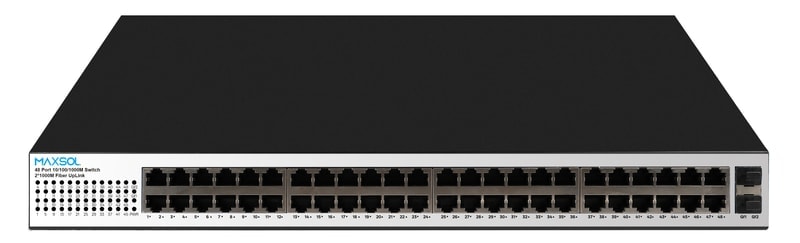
The 48-port Gigabit PoE switch with two uplink ports and 400W budget has a documented 400W total PoE budget. Ports 1–48 support IEEE 802.3af/at up to 30W per port.
A 400W total budget can suit a larger number of lower-to-medium power devices, provided the combined calculated load stays within the budget. However, 48 PoE ports multiplied by 30W equals more than 400W, so not every port can necessarily deliver its maximum simultaneously.
This is exactly why a shared power calculation is essential. The switch’s 30W per-port capability solves the individual-port test for suitable devices; the 400W total budget remains the shared-limit test.
Common PoE budgeting mistakes
Several avoidable errors lead to unstable surveillance systems:
- Using the number of ports as the power budget. Port count and watts are separate limits.
- Calculating from average camera power. Use maximum documented demand or a justified simultaneous-load model.
- Ignoring night operation. IR illumination and other functions may increase demand across many cameras at once.
- Treating all ports as equal. Some switches provide higher power or different standards on selected ports only.
- Confusing a PSU rating with a PoE budget. Verify the manufacturer’s stated usable PoE allocation.
- Omitting non-camera PoE devices. Wireless equipment and access-control devices consume from the same shared pool.
- Using no headroom. A calculation that exactly equals the budget leaves no tolerance for expansion or peak conditions.
- Overlooking cable condition and distance. A compatible power figure does not make an unsuitable cable run reliable.
- Forgetting the upstream source. UPS, inverter, solar and AC supply sizing must support the overall system, not only camera demand.
Recheck the design before installation
Before installation, perform a final desk review and an on-site commissioning check.
Design review checklist
- Confirm the exact camera and powered-device models.
- Confirm each device’s maximum power and required PoE standard.
- Check every proposed port against the device’s individual power requirement.
- Add all simultaneous loads and compare the result with the documented switch PoE budget.
- Include 20% to 30% headroom, or a justified project-specific allowance.
- Verify cable type, route length, termination quality and outdoor installation requirements.
- Check uplink capacity and port availability independently from PoE power.
- Confirm the AC, UPS, inverter or solar-backed source can support the switch design.
Commissioning check
After installation, test the conditions most likely to produce peak demand. Depending on the device functions, this may include night-mode operation, IR activation, PTZ movement and simultaneous startup. Monitor for cameras restarting, dropping from the network or losing functions under load.
If a design is close to the switch’s limit, do not rely on it remaining stable after a camera firmware change, configuration adjustment or future expansion. Recalculate before adding devices.
FAQ
How much PoE power should I allow per security camera?
Use the camera manufacturer’s stated maximum power requirement rather than a generic allowance. Camera power varies materially with features such as IR, PTZ movement, heating and lighting.
Is a 30W PoE port suitable for every camera?
No. A 30W port may suit devices whose documented requirement and PoE standard are within that limit, but a higher-power device can require IEEE 802.3bt or a different power arrangement. Check the device data sheet and the exact switch port capability.
Can I use every PoE port at maximum power?
Only if the switch’s documented total PoE budget supports the combined load. In many switches, the sum of the maximum per-port figures is greater than the shared budget.
Should I leave spare PoE budget for future cameras?
Yes. Include headroom in the initial design and recalculate whenever equipment is added. Spare physical ports do not guarantee spare power capacity.
Calculate the device schedule first, then compare the 120W, 300W and 400W Maxsol options against your required port count, simultaneous load, cable distance, power source, environmental conditions and management requirements.