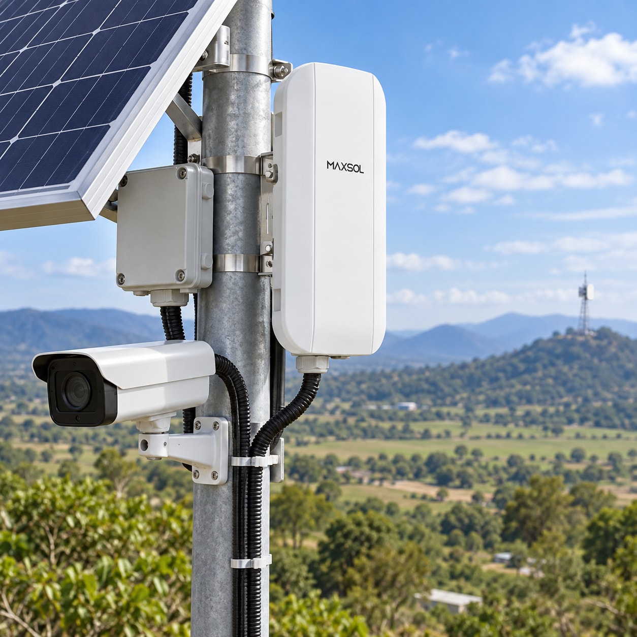
Solar Power for CCTV: Pre-Deployment Checklist
Use this checklist to verify CCTV loads, solar access, PoE interfaces, autonomy, monitoring and commissioning evidence before procurement.
By Maxsol Team

A solar power for CCTV deployment checklist should establish the full electrical load, available solar resource, required autonomy, interface compatibility and network design before equipment is purchased. It should also define how the completed site will be measured, monitored and maintained.
The main deliverable is not simply a panel-and-battery specification. It is an evidence pack showing what the surveillance system consumes by day and night, where the panel can receive reliable design-month sunlight, how video will be recorded and transmitted, and what must happen during prolonged poor weather.
| Review area | Evidence to collect before procurement | Decision it supports |
|---|---|---|
| Cameras and recording | Datasheets, measured loads, operating modes and recording plan | Total day and night energy demand |
| Backhaul | Radio, router, switch and modem loads; link survey | Continuous network load and connection method |
| Solar access | Shade survey, orientation, mounting photographs and design-month conditions | Panel location and solar input assumptions |
| Power interfaces | Voltage, polarity, PoE type, pinout, port count and cable length | Converter, switch and cabling compatibility |
| Resilience | Autonomy target, recovery time and load priorities | Battery and array design objectives |
| Environment | Temperature, dust, moisture, wind, corrosion and security exposure | Enclosure, mounting and protection requirements |
| Operations | Monitoring points, access method and maintenance responsibility | Support and maintenance plan |
| Acceptance | Measured energy and network criteria | Commissioning sign-off |
Document cameras, recording and backhaul loads
Begin with a complete equipment schedule. Listing only the cameras will understate the load because an operational CCTV site may also include PoE conversion, switches, edge recorders, wireless radios, routers, cellular equipment, heaters, fans and control electronics.
For each device, record:
- Manufacturer and model number
- Quantity
- Input voltage and acceptable voltage range
- Typical and maximum power consumption
- Day and night operating modes
- Start-up or peak demand
- PoE standard or passive power arrangement
- Hours of operation per day
- Whether the device is essential or can be disconnected
- Source of the figure, such as a datasheet or site measurement
Separate day and night camera demand
Infrared illumination can increase a camera’s night-time consumption. PTZ movement, integrated white lights, heaters and other functions can also change the load. A nameplate value alone may not explain when these loads occur.
Create at least two load states:
- Day load: cameras, recording and communications under normal daylight conditions.
- Night load: cameras with their expected infrared, lighting or low-temperature functions active.
Where equipment has variable demand, retain both the expected operating value and the manufacturer’s maximum value. Do not base the system on an unverified “average” that excludes night operation.
Include recording equipment
Confirm whether video will be:
- Recorded on camera memory cards
- Stored on an edge NVR
- Sent continuously to a remote recorder
- Transmitted only after an event
- Stored locally and reviewed remotely when required
An NVR, storage device or edge computer can be a significant continuous load. Recording architecture also affects backhaul traffic. Continuous multi-camera video generally requires more stable capacity than event clips or occasional remote viewing.
Time synchronisation, storage retention, image resolution, frame rate and codec settings should be documented because they influence storage and network demand even when their direct electrical impact is modest.
Account for the entire backhaul chain
Include every device between the camera and the destination network: Ethernet switches, PoE injectors, wireless CPE units, routers and modems. Add conversion losses rather than assuming that battery output and device consumption are identical.
The Maxsol CPE295 directional wireless CPE is one architecture example. Its documented features include 5.8GHz operation, a 2x2 14dBi directional MIMO antenna, one Gigabit LAN port, IEEE 802.3af/at or 9–48V DC power support, and 6.5W full-load consumption. Range and rate labels do not guarantee usable site throughput; line of sight, interference, alignment and link conditions still require verification.
For broader architecture planning, review the practical sequence in this guide to building a solar-powered CCTV system for remote areas.
Survey shade, mounting and environmental exposure
A solar survey must represent the worst practical solar period, not merely the conditions observed on installation day. In South Africa, a clear summer inspection can conceal winter shade from terrain, structures or vegetation.
Record the following at the proposed panel position:
- Horizon obstructions
- Morning and afternoon shade
- Seasonal vegetation growth
- Nearby buildings, poles and equipment
- Panel orientation and tilt options
- Available mounting height and structure
- Cable route to the equipment enclosure
- Risk of future development blocking sunlight
- Safe access for inspection and cleaning
In the Southern Hemisphere, a generally north-facing panel position is often considered first, but the correct orientation must follow the actual site survey, terrain, shade pattern and design objective. A compass direction alone is not proof of adequate solar access.
Use a defined design month
The project team should agree on the solar conditions against which the system will be reviewed. This is commonly a low-solar design month or another conservative project period. Record the solar data source, location assumptions, tilt assumptions and any loss factors used.
Do not substitute annual average sunshine for design-month evidence. A system may produce excess energy during favourable months while still failing its autonomy or recovery objective during the selected low-solar period.
Inspect environmental and mechanical risks
The enclosure and mounting system may face more than rain. Site conditions can include:
- High internal enclosure temperatures
- Dust and fine airborne material
- Condensation and moisture
- Coastal or industrial corrosion exposure
- Strong winds and panel uplift forces
- Lightning and surge exposure
- Insects or small animals entering cable routes
- Vegetation contact
- Theft, tampering and vandalism
- Vehicle, livestock or machinery impact
Document cable glands, drainage, ventilation strategy, equipment spacing and mounting materials. Confirm that heat-producing equipment will not create unacceptable enclosure temperatures.
Earthing, bonding and surge protection should be designed for the site and installed according to the relevant equipment requirements and applicable local practices. Do not assume that a metal pole or cabinet automatically provides an effective earth path.
Confirm voltage, PoE and data interfaces
“PoE camera” is not a sufficient compatibility description. The project must verify voltage, polarity, power negotiation, pinout and available power at the far end of the cable.
For every connected device, confirm:
- DC input voltage range
- Maximum operating power
- Connector type
- Centre-positive or other polarity
- Standards-based or passive PoE
- Required PoE mode and pinout
- Ethernet speed
- Maximum permitted cable length
- Outdoor cable and surge-protection requirements
- Whether a converter, injector or switch is required
Distinguish standards-based PoE from voltage conversion
A converter that produces a PoE-level voltage does not necessarily perform IEEE PoE detection and negotiation. Passive power should not be connected to equipment merely because the voltage appears suitable.
The Maxsol POE24V DC-to-PoE converter accepts 12–36V DC and provides an adjustable 12–57V PoE output, Gigabit Ethernet and an LCD voltage display. Its documented continuous load when converting 12V to 48V is no more than 30W. These facts do not establish IEEE PoE negotiation, so installers must verify the receiving device’s voltage, polarity, pinout, protocol and power demand.
Also calculate voltage drop on the DC feed. Long low-voltage DC runs can lose substantial voltage and power, especially when current rises. It is often better to decide the enclosure location, cable lengths and distribution voltage together rather than treating cabling as a later installation detail.
Check every port and data path
A camera can receive power yet still fail to communicate correctly. Confirm:
- Switch and injector port count
- Per-port and total PoE budget
- Ethernet speed and duplex support
- VLAN or addressing requirements
- Recorder compatibility
- Remote management method
- Wireless bridge addressing and operating mode
- Link capacity under expected video traffic
- Cybersecurity and credential requirements
- Time synchronisation source
Perform a line-of-sight and path assessment for directional wireless links. Clear visual line of sight is useful but may not be enough; terrain, obstructions, alignment, mounting movement and radio interference can affect performance.
Set autonomy, recovery and load-priority objectives
Autonomy is the period for which the CCTV system must operate without useful solar input. It is a project requirement, not a universal number.
Define autonomy in hours or days and state:
- Which equipment must remain operational
- Whether the target applies at normal or maximum load
- The acceptable battery discharge limit
- Environmental assumptions
- What happens when the limit is reached
- How quickly the system should recover after sunlight returns
A higher autonomy requirement usually increases stored-energy needs, but battery capacity cannot be considered separately from solar-array recovery. A large battery with insufficient charging capacity may take too long to recover after poor weather.
The Maxsol CS12060 solar power system documents a 120W monocrystalline panel, a 12.8V 60Ah 768Wh LiFePO4 battery, an MPPT controller and three DC 12V outputs. These specifications are useful for comparison, but they do not establish runtime for a particular CCTV site. Runtime depends on the verified load, conversion losses, solar conditions, control settings, usable stored energy and recovery objective.
For detailed calculation steps, use the guide to sizing an off-grid solar power system for CCTV after the site evidence and load schedule have been completed.
Define load priorities before a low-energy event
A controlled load-shedding plan can preserve the most important surveillance functions. One possible priority structure is:
| Priority | Typical function | Low-energy response |
|---|---|---|
| Essential | Critical camera, recording and primary backhaul | Keep active for the defined autonomy period |
| Important | Secondary cameras or non-critical network equipment | Disconnect at a lower battery threshold |
| Deferrable | Auxiliary lighting or convenience equipment | Disable early or operate only when energy permits |
The actual priorities must follow the security objective. Turning off a backhaul radio may preserve local recording but remove live alarms. Turning off an edge recorder may retain live viewing while losing evidence. The project owner must approve these trade-offs before deployment.
Specify how equipment restarts after low-voltage shutdown. Simultaneous restart can create a peak load, while repeated on-off cycling can destabilise cameras and radios. Recovery thresholds and restart sequencing should be documented where the controller supports them.
Plan monitoring, maintenance and physical access
Monitoring should reveal declining energy availability or network performance before the site becomes unavailable. A camera heartbeat alone cannot show whether the battery is recovering properly.
Useful monitoring points include:
- Battery voltage or state indication
- Solar charging input
- Load current or power
- Controller status and alarms
- Enclosure temperature
- Camera and recorder availability
- Wireless link status
- Packet loss and latency trends
- Storage health and remaining capacity
- Time synchronisation status
- Low-voltage shutdown and restart events
A voltage reading is not always a complete measure of available battery energy, particularly while charging or under load. Decide what each monitored value means, how often it is recorded and what threshold triggers inspection.
Design for safe maintenance access
Before choosing the final mounting position, determine how technicians will:
- Reach and clean the panel
- Open the enclosure safely
- Inspect glands and seals
- Test battery and controller connections
- Realign or replace a wireless radio
- Download recordings if the backhaul is unavailable
- Isolate power before service
- Control vegetation and remove obstructions
A panel mounted high enough to discourage theft may require specialised access equipment. A cabinet hidden for security may have poor ventilation or radio visibility. These conflicts should be resolved during design, not left to the installer on site.
Create a maintenance schedule based on actual exposure. Dust, bird fouling, vegetation growth, loose fasteners, cable damage, corrosion and water ingress are all conditions that can develop after commissioning. Record who owns each inspection task and how faults will be escalated.
Commission with measured energy and network evidence
Commissioning should demonstrate that the installed system matches the design evidence. A camera appearing online for a few minutes is not sufficient acceptance for a solar-powered site.
Use calibrated or suitably accurate instruments and retain readings with the site records.
Verify the electrical system
Commissioning measurements should include, where applicable:
- Panel open-circuit and operating values under the observed conditions.
- Controller input, battery and load readings.
- Battery voltage at rest and under the operating load.
- Voltage at the camera or powered device, not only at the cabinet.
- Total day load after the system has stabilised.
- Total night load with infrared or other night functions active.
- Start-up behaviour after power is restored.
- Converter and cable temperature under expected load.
- Low-voltage alarm, shutdown and restart behaviour, if safely testable.
- Polarity, protective devices, earthing and surge-protection installation.
Record weather, time and operating state alongside the readings. A current value without knowing whether the battery was charging or whether camera infrared was active has limited evidential value.
Avoid an uncontrolled deep-discharge test merely to prove autonomy. The acceptance method should be agreed in advance and should not unnecessarily stress the battery or leave the surveillance site unprotected.
Test the complete network and recording path
Network commissioning should cover more than a successful ping. Confirm:
- Every camera can be viewed and managed
- Required streams reach the recorder
- Video is stored at the specified settings
- Recorded footage can be retrieved
- Timestamps are correct
- Packet loss, latency and throughput meet project criteria
- Wireless links remain stable over an agreed observation period
- Remote access works through the intended route
- Alarms and health notifications reach the responsible team
- Local recording continues during a backhaul interruption, if specified
- Services recover correctly after a power interruption
For wireless backhaul, retain radio alignment, signal and link-quality readings together with the test traffic results. Do not use a radio’s labelled maximum range or data rate as commissioning proof.
Create a signed acceptance record
The final record should contain:
- Installed equipment models and serial numbers
- As-built wiring and network diagrams
- Panel orientation, tilt and mounting photographs
- Cable routes and lengths
- Protection-device details
- Configuration backups
- Day and night energy readings
- Wireless and network test results
- Recording and retrieval test results
- Monitoring thresholds
- Maintenance instructions
- Outstanding limitations or deviations
Any difference between the design and installed equipment should trigger a compatibility and load review. A substituted camera, radio or converter may alter both power demand and interface requirements.
Procurement gate: questions to answer before ordering
A project is ready for procurement only when the team can answer these questions with documented evidence:
- What is the complete maximum day load?
- What is the complete expected and maximum night load?
- Which devices operate continuously?
- Where is video recorded, and for how long?
- What traffic must cross the backhaul?
- Has the wireless or wired path been surveyed?
- What is the design-month solar assumption?
- Is the panel position free of material seasonal shade?
- What autonomy and recovery objectives have been approved?
- Which loads are disconnected first during low energy?
- Are voltage, polarity, PoE protocol and pinout confirmed?
- Have DC and Ethernet cable losses and limits been reviewed?
- Is the enclosure suitable for the documented exposure?
- Can technicians safely access every service point?
- What energy and network readings will define acceptance?
- Who will monitor and maintain the system?
Missing answers should be treated as design actions, not assumptions. This avoids selecting a battery before the night load is known, a panel before the shade survey is complete, or a PoE converter before the camera interface has been verified.
As a practical next step, compare the linked Maxsol architecture examples against the project’s actual port count, day and night load, cable and wireless distance, voltage and PoE requirements, environmental exposure, autonomy target and management needs. They are not a tested compatible bundle, so compatibility and expected performance must be established for the specific deployment.