How to Build Solar-Powered CCTV for Remote Sites
Plan a remote solar CCTV system from site survey to acceptance, covering recording, backhaul, power interfaces, protection and outage testing.
By Maxsol Team

If your goal is to build a solar-powered CCTV system for remote areas, treat it as one integrated power, surveillance and communications project. Start by confirming camera coverage and access conditions, then select the recording and backhaul architecture, calculate every electrical load, verify power interfaces, protect the installation and test it under night-time and outage conditions.
A reliable design does not begin with a panel or battery size. It begins with a go/no-go site survey and a documented load schedule. Cameras, recorders, switches, radios, cellular modems and converters are separate components unless explicitly supplied as a tested system, so every voltage, connector, protocol and power limit must be checked.
Survey coverage and remote-site constraints
The survey must establish whether the proposed site can deliver useful video, collect enough solar energy and communicate reliably. A remote pole with clear sunlight may still be unsuitable if the camera cannot identify the required subject or if a wireless path is obstructed.
Define the surveillance objective before choosing equipment:
- What must be detected, observed, recognised or identified?
- What is the required field of view?
- At what distance must the target be useful in recorded footage?
- Is colour required at night, or is infrared imaging acceptable?
- Must the system record continuously or only on events?
- How many days of local retention are required?
- Who needs live access, and how quickly must recorded evidence be retrieved?
- What happens when the backhaul fails?
Inspect the proposed camera position at the intended mounting height where practical. Check vegetation, moving branches, dust, headlight glare, shadows and objects that could obstruct or repeatedly trigger analytics. Night-time illumination should also be assessed because built-in infrared lighting can reflect from nearby surfaces, fencing, insects or dust.
Solar exposure must be checked across the full day rather than only at the time of the visit. Look for seasonal shading from trees, terrain, structures and future vegetation growth. Also assess whether the panel position will be vulnerable to theft, deliberate damage, bird fouling or debris.
South African outdoor sites may face combinations of heat, thunderstorms, wind, dust, coastal corrosion and veld-fire exposure. Conditions vary substantially by location, so enclosure materials, cable protection, mounting hardware and maintenance intervals should be selected for the actual site rather than a generic regional assumption.
Go/no-go survey checks
| Survey item | Proceed when | Redesign or stop when |
|---|---|---|
| Camera view | The required subject occupies enough of the image for the stated surveillance objective | The view is blocked, too distant or dependent on unsuitable digital zoom |
| Solar access | The proposed panel area has a practical, secure and largely unshaded solar window | Persistent shading or an unsafe mounting location cannot be corrected |
| Wireless path | The endpoints have suitable line of sight and adequate clearance | Terrain, buildings or vegetation block the path with no viable alternative |
| Cellular option | Signal and usable data performance are confirmed at the intended equipment position | Coverage is intermittent or unable to support the required service |
| Mounting structure | The structure can safely support the panel, enclosure, camera, radio and wind loading | Strength, stability or authorised access cannot be confirmed |
| Maintenance access | Technicians can safely reach serviceable parts | Routine inspection would require unacceptable risk or disruption |
| Equipment security | Enclosures, fasteners and cables can be protected | Theft or tampering risk cannot be reduced to an acceptable level |
| Earthing and protection | A site-appropriate protection plan can be implemented | Surge and lightning exposure cannot be addressed responsibly |
A failed check does not always end the project. It may require a different camera position, a relay point, local-only recording, a larger installation area or a revised surveillance objective. Do not approve the design until all critical uncertainties have an owner and a resolution.
Choose the recording and backhaul architecture
Remote CCTV can record at the camera, at an on-site recorder or at a remote location reached through wireless or cellular backhaul. A hybrid architecture is often more resilient because it preserves local evidence during communications outages while still providing remote health monitoring or selected live access.
| Architecture | Main advantage | Main limitation | Suitable use |
|---|---|---|---|
| Camera-edge storage | Low power demand and no separate recorder | Storage is distributed and may be lost with the camera | Small systems where local retrieval is acceptable |
| On-site recorder | Central local storage for several cameras | Adds continuous power demand and another enclosure component | Multi-camera sites requiring organised retention |
| Point-to-point wireless | Can carry video without recurring cellular data use | Requires a viable radio path and another powered endpoint | Sites with line of sight to a networked building or mast |
| Cellular backhaul | Does not require a nearby fixed network endpoint | Coverage, data use and carrier performance may vary | Remote monitoring where suitable mobile service is verified |
| Hybrid local recording and backhaul | Retains evidence locally during network interruptions | More components and configuration work | Sites where both resilience and remote access matter |
Local recording
Size local storage from the cameras’ actual configured bitrates, recording schedule, resolution, frame rate, compression and required retention period. Event recording can reduce storage use, but it creates dependence on motion detection or analytics being configured correctly.
Confirm how recordings are retrieved after a communications failure. A system that stores footage successfully but requires unsafe physical access to export it may not meet the operational requirement.
Where an on-site recorder is used, include its full power consumption, storage drive demand and start-up behaviour in the energy budget. Cameras and recorders are not implied to be included with any linked solar or networking component in this guide.
Wireless backhaul
A point-to-point bridge needs line of sight, suitable antenna alignment, mounting rigidity and a clear frequency plan. The usable throughput at the site matters more than a headline wireless rate.
The Maxsol CPE295 5.8GHz wireless CPE documents 5.8GHz operation, a 2×2 14dBi directional MIMO antenna, one Gigabit LAN port, IEEE 802.3af/at or 9–48V DC power support, and 6.5W full-load consumption. Product range or wireless-rate labels do not guarantee application throughput or a particular link distance. Verify line of sight, interference, mounting alignment, fade margin and applicable local radio rules.
Cellular backhaul
Cellular can support alerts, health monitoring, selected playback or live video where coverage is suitable. Test at the proposed antenna height and enclosure position rather than relying only on a mobile phone reading at ground level.
Calculate likely data use from the actual streaming policy. Continuous high-bitrate upload has very different power and data implications from alarm clips or occasional operator access. Confirm modem supply voltage, peak power demand, antenna arrangement, carrier support and recovery behaviour after a dropped connection.
Establish the complete power budget
List every device that draws energy, including equipment that is easy to overlook:
- Cameras, including infrared illuminators, heaters or other enabled features
- Local recorder and storage drives
- PoE or Ethernet switch
- Wireless CPE or access point
- Cellular modem and router
- DC-to-DC or DC-to-PoE converters
- Enclosure fans, heaters or control electronics
- Auxiliary lighting, sensors and relays
- Expected cable and conversion losses
Use measured input power from the intended configuration where possible. Datasheet maximums are useful for checking worst-case limits, but actual measurements at day and night provide stronger design evidence.
The basic daily load is:
Daily energy in Wh = total continuous input power in W × 24 hours
Hypothetical load example
The figures below are assumptions for illustrating the method. They are not measured product performance and must not be used as a final system specification.
| Hypothetical load | Quantity | Assumed input per device | Subtotal |
|---|---|---|---|
| Cameras in night mode | 3 | 8W | 24W |
| Local recorder | 1 | 12W | 12W |
| Network switch | 1 | 5W | 5W |
| Wireless radio | 1 | 6.5W | 6.5W |
| Total connected load | 47.5W |
At a constant hypothetical 47.5W, the load would require 1,140Wh per day before allowing for conversion losses, cable losses, temperature effects, battery limits, weather reserve or ageing margins. Peak load and device start-up demand must also remain within the ratings of the controller, battery protection, wiring and each converter.
This is only the load calculation. Panel and battery selection should be completed using the off-grid solar sizing guide for CCTV systems, with site-specific solar inputs and an appropriate autonomy target. Do not treat nominal battery watt-hours as fully usable delivered energy.
Specify solar storage and power interfaces
Once the load schedule is complete, select the solar and storage system around the required input energy, output voltage, peak current, autonomy target and environmental conditions.
The Maxsol CS12060 120W and 768Wh LiFePO4 solar system documents a 120W monocrystalline panel, 12.8V 60Ah battery with 768Wh nominal energy, an MPPT controller and three DC 12V outputs. RS485 is optional.
Those figures do not establish universal runtime or confirm suitability for a particular CCTV load. Verify the current datasheet and supplied configuration for:
- Controller PV voltage, current and power limits
- Output current limits per port and in total
- Battery charging temperature requirements
- Low-voltage and overcurrent protection behaviour
- Cable lengths, conductor sizes and connector types
- Required autonomy after site-specific losses and reserve margins
- Restart behaviour after low-voltage shutdown
Nominal battery energy is not the same as energy delivered to the cameras. Controller consumption, converter efficiency, voltage drop, operating temperature and protection thresholds all affect usable energy.
Verify DC and PoE compatibility
“PoE” does not by itself confirm that two devices can be connected safely. Check the required output voltage, polarity, pinout, power limit and whether the powered device expects standards-based detection or passive power.
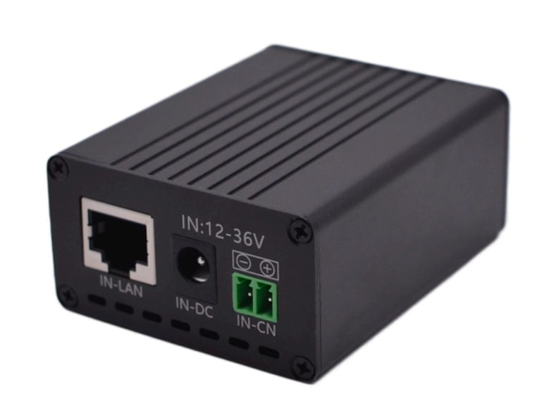
The Maxsol POE24V DC-to-PoE converter accepts 12–36V DC and provides adjustable 12–57V PoE output, Gigabit Ethernet and an LCD voltage display. Its documented continuous-load limit for 12V-to-48V operation is at most 30W. A maximum conversion efficiency of up to 94% is not a guaranteed design value.
IEEE powered-device detection or negotiation is not established by those facts. Before connecting a camera, radio or switch, verify:
- Input voltage throughout the battery’s operating range
- Required PoE output voltage
- Device power under maximum load
- Polarity and powered Ethernet pinout
- Whether active negotiation or passive power is required
- Converter thermal and continuous-load limits
- Connector and cable compatibility
The solar system, converter and wireless CPE discussed here are selection examples, not a tested compatible bundle. Interface verification remains essential even when voltage ranges appear to overlap.
Plan mounting, cabling and protection
The physical installation must keep the panel exposed to sunlight while protecting the camera’s view, radio alignment and enclosure access. Avoid placing the panel where it shades the camera, obstructs the radio path or makes maintenance unsafe.
Use a rigid structure designed for the combined panel, mast, enclosure and equipment loading. Camera and directional-radio brackets must resist movement because a small shift can alter the camera scene or reduce wireless link quality.
Cable planning
Keep low-voltage cable runs as short as practical. Voltage drop is especially important on 12V circuits because a modest drop can cause equipment resets or low-voltage shutdown even while the battery still contains energy.
Document:
- Cable conductor size and length
- Maximum branch current
- Connector type and weather sealing
- Fuse or breaker position and rating
- Voltage at the source and at the load
- Ethernet category and outdoor suitability
- Separation between data, DC and other services
- Drip loops, strain relief and entry-gland arrangement
Where fibre, PoE switching, batteries and outdoor enclosures are combined, use the outdoor PoE switch box, power, fibre and battery planning guide to organise interfaces and service access.
Environmental and electrical protection
Select an enclosure suited to the actual dust, water, corrosion, temperature and tampering exposure. A sealed box also traps heat, so check the thermal output of recorders, converters, switches and radios under the expected ambient conditions.
Provide appropriately designed overcurrent, surge and lightning protection. Earthing and bonding should be planned for the complete structure, including the panel frame, mast, enclosure and incoming copper services where applicable. These measures should be specified and installed by suitably qualified people for the site conditions.
Protect exposed cables against UV, abrasion, rodents and deliberate cutting. Keep connectors out of standing water, face cable entries downward where practical and do not rely on insulating tape as the primary weather seal.
Commission night operation and outage recovery
Commissioning must prove that the system works in its highest-load condition, records usable evidence and returns to service after power or communications interruptions. A daytime live view alone is not an acceptance test.
1. Confirm the installed configuration
Record model details, firmware versions, supply voltages, camera settings, recording schedules, IP addresses and radio or modem configuration. Label cables and power branches so future technicians can isolate components without guesswork.
2. Test full night-time load
Operate all cameras with their intended night settings active. Confirm infrared illumination, exposure, focus, motion blur and reflections. Measure input voltage and current at the battery system and at critical loads.
Check that converters, connectors and enclosures do not show abnormal heating. Confirm the total load remains within every continuous-output limit.
3. Prove recording and retrieval
Create a test event in each camera view, then retrieve the footage through the intended operational method. Confirm:
- Correct date and time
- Required image detail
- Continuous or event recording as specified
- Audio only where intentionally configured
- Expected retention settings
- Successful export in the required format
- Continued local recording during a backhaul interruption
4. Test backhaul performance
For wireless links, record signal and noise indicators, negotiated link information and practical application throughput. Test during conditions representative of expected operation where possible.
For cellular systems, confirm reconnection after signal loss or modem restart. Ensure video settings do not exceed the intended data policy.
5. Test outage and restart behaviour
Use a controlled, safe test procedure rather than deliberately deep-discharging the battery. Simulate relevant failures individually:
- Loss and restoration of PV input
- Restart of the DC power system
- Backhaul interruption
- Recorder restart
- Camera branch power cycle
- Radio or modem power cycle
Verify that devices restart in a stable order, cameras resume recording, the backhaul reconnects and no component remains latched off. Confirm the system clock remains accurate after a prolonged communications interruption.
6. Build the acceptance evidence pack
The final handover should include enough evidence for another technician to understand and support the site:
- Survey photographs and final installation photographs
- Camera views in daylight and darkness
- Sample exported recordings
- Load schedule and measured day/night readings
- Solar, battery and converter configuration
- Wireless or cellular test results
- Cable and fuse schedule
- Device configuration backups
- Network diagram and IP address schedule
- Maintenance access and isolation procedure
- List of unresolved limitations or assumptions
Acceptance should be based on objective criteria agreed before installation. Examples include usable coverage of defined areas, successful local recording during backhaul loss, stable night operation and automatic recovery after a controlled outage.
Common mistakes to avoid
- Sizing the system from camera wattage alone while excluding radios, recorders and conversion losses
- Assuming nominal battery capacity equals usable delivered energy
- Selecting a wireless bridge from a distance label without surveying line of sight and interference
- Using a cellular connection without measuring service at the equipment position
- Treating all PoE inputs as electrically interchangeable
- Testing only during daylight, before infrared loads switch on
- Mounting directional radios on flexible poles or brackets
- Omitting local recording when the backhaul is not continuously reliable
- Using indoor connectors, patch leads or enclosures outdoors
- Failing to document restart behaviour after low-voltage or communications failure
- Accepting a live image without testing recorded evidence and export
Frequently asked questions
Can a solar CCTV system operate continuously?
It can be designed for continuous operation, but there is no universal 24/7 runtime guarantee. Success depends on the actual load, usable battery energy, solar input, weather reserve, temperature, conversion losses and shutdown thresholds. These factors must be calculated and then confirmed during commissioning.
Does remote CCTV require internet access?
No. Cameras can record locally at the edge or to an on-site recorder without internet access. A network connection is required only for functions such as remote live view, alerts, off-site recording, remote administration or automatic health monitoring.
Is wireless backhaul better than cellular?
Neither is always better. A point-to-point wireless link may offer predictable local connectivity where clear line of sight exists. Cellular is useful where there is no network endpoint, but coverage and data use must be verified. Hybrid local recording protects evidence when either backhaul type fails.
Can several cameras share one solar system?
Yes, if their combined continuous and peak loads remain within the solar controller, battery, outputs, converters and wiring limits, and if the site-specific energy calculation supports the required autonomy. Each branch should be documented and appropriately protected.
The practical next step is to compare the linked Maxsol models with the project’s actual port count, measured load, link distance, power interfaces, environmental exposure and management requirements. Confirm current datasheets and interface compatibility before approving procurement or installation.