Outdoor PoE Switch Box with Battery Backup: SA Guide
Choose an outdoor PoE switch box with battery backup for South African sites: assess IP rating, fibre uplinks, UPS capacity, PoE load and protection.
By Maxsol Team

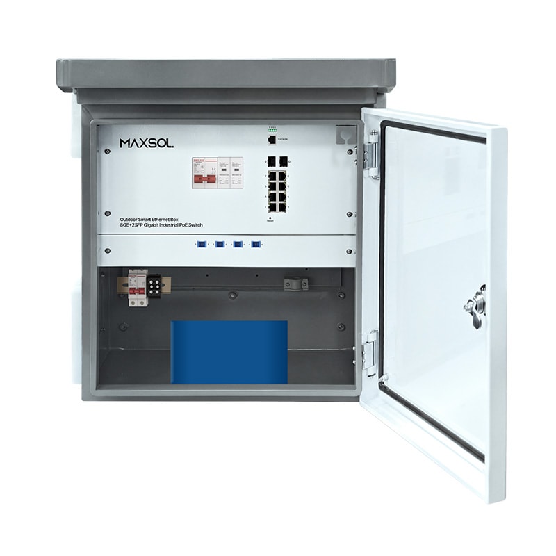
An outdoor PoE switch box with battery backup combines network switching, power distribution and protected outdoor housing in one installation point. It can simplify CCTV, wireless bridge and perimeter-network deployments where cameras or access points need both data and PoE power away from the main equipment room.
For South African projects, the most important decision is not simply whether a box has a battery. Confirm that the enclosure suits the site, the switch has the right management level and uplink type, the AC supply is suitable, and the UPS and battery can support the actual connected load for the required outage period. Backup duration is never fixed: it changes with PoE consumption, battery condition, temperature and the number of devices operating.
Why integrate switching and power outdoors
An integrated outdoor PoE box places the switch close to field devices while retaining a central, weather-resistant location for power and fibre or Ethernet uplinks. Instead of fitting a separate enclosure, PoE switch, power supply and backup equipment, the installer can plan one coordinated field cabinet.
This approach is particularly useful when devices are spread across a site, such as:
- IP cameras along a perimeter, entrance road or parking area;
- wireless access points serving an outdoor work area;
- point-to-point or point-to-multipoint CPE equipment;
- gate intercoms, access-control equipment and monitoring devices;
- remote structures where a local fibre hand-off is more practical than long copper runs.
The benefit is not that every installation becomes simple. Outdoor equipment still needs careful earthing, cable routing, load assessment and maintenance access. However, a purpose-designed box can reduce the number of individual components that must be mounted, wired and protected in the field.
For fibre-linked sites, 2 Gigabit SFP slots can be valuable because they allow a copper PoE access layer at the edge while providing fibre uplinks back to the core network. Before specifying SFP modules, confirm the fibre type, connector type, link distance, wavelength, speed and compatibility requirements for the complete network.
A remote PoE box is also not a substitute for good network design. Consider the available uplink bandwidth, camera bitrates, wireless backhaul demand and what happens when the uplink fails. A full PoE budget does not automatically mean sufficient network capacity.
Enclosure and environmental checks
Start with the physical environment. The enclosure is the first line of defence against water, dust, UV exposure, insects, tampering and cable-entry problems.
An IP65 rating indicates protection against dust ingress and water jets, but it should not be interpreted as permission to install equipment in any condition. Positioning, mounting and workmanship still determine whether the finished installation remains reliable.
Check the mounting position before choosing the box
Choose a solid mounting surface that gives installers safe, repeatable access. Avoid locations where the enclosure may be submerged, exposed to continual spray, struck by vehicles or opened without suitable working clearance.
Review these conditions during the site survey:
- Water path: Cable glands should face and drain appropriately. Do not create cable runs that guide water directly into glands or openings.
- Solar exposure: Direct sun can raise internal temperatures substantially. Where possible, choose a shaded or protected position without blocking ventilation features designed into the enclosure.
- Condensation: A watertight enclosure can still experience internal condensation through temperature cycling. Assess the location, cable-entry sealing and maintenance plan.
- Corrosion: Coastal, industrial and high-humidity locations may require more careful attention to mounting hardware, cable glands and periodic inspection.
- Physical security: Put the box where it cannot be easily tampered with, while ensuring authorised technicians can reach it.
- Cable strain: Support heavy outdoor cable runs independently. Do not let cables pull on glands, fibre connectors or internal terminations.
The supplied specification should confirm the operating temperature range, permissible humidity, mounting method, dimensions, grounding points and cable-entry arrangement. Do not assume these values from the IP rating alone.
AC input, earthing and surge protection
Power quality deserves the same attention as networking. Confirm the local AC circuit, isolation method, breaker arrangement and earthing approach before installation. A qualified electrician should handle mains connections and establish whether the available supply and protective devices meet the project requirements.
For outdoor installations, assess surge risk across all conductive paths:
- AC power entering the box;
- copper Ethernet runs to cameras, radios or other devices;
- external antenna or radio equipment where applicable;
- earth bonding between equipment at different locations.
A switch box may include power-related functions, but do not assume it has a particular surge-protection rating or that it replaces a coordinated site-wide lightning protection strategy unless that product documentation explicitly says so. Confirm whether external AC and Ethernet surge protective devices are required, how they must be earthed, and whether they affect warranty or installation requirements.
Common mistakes include fitting an Ethernet protector without a low-impedance earth path, bonding equipment inconsistently, or assuming fibre removes the need to protect locally powered field devices. Fibre provides electrical isolation in the data path, but the remote PoE box, AC feed and copper device runs can still need protection.
Managed versus unmanaged switching
Choose managed switching when the site needs visibility and control. Choose an unmanaged design when the network is straightforward, the operating model favours simple local configuration and the available hardware functions meet the project’s needs.
When Layer 2 management is worth it
A managed switch gives the network team tools to segment, monitor and troubleshoot the edge network. On multi-camera, multi-tenant or operationally sensitive sites, this can be a major advantage.
Layer 2 management is commonly selected where you need to:
- separate cameras, wireless users, access control and administration with VLANs;
- apply and maintain network policies centrally;
- diagnose a link, port or topology issue without a site visit;
- monitor port status and PoE-related events where supported;
- manage uplink behaviour and reduce the risk of an incorrectly connected field device affecting the broader network.
Management features need planning to be useful. Specify a secure management VLAN, restrict administration access, document addressing and credentials, and decide who will receive or act on alerts. A managed switch installed with no management plan can add complexity without delivering operational value.
The SBOX2802SFG-I managed industrial smart Ethernet box combines IP65 housing, 8 Gigabit PoE ports, 2 Gigabit SFP slots, Layer 2 management, AC100–240V input and a built-in 240W DC55V UPS module. It is a suitable starting point for evaluating a managed outdoor edge design, subject to confirming the complete power and battery configuration for the project.
When an unmanaged switch is the practical option
An unmanaged switch can be appropriate for a small, fixed network with a known topology, especially where the installer needs simple deployment and there is no requirement for centrally managed Layer 2 functions.
The SBOX1802SFG-I unmanaged industrial smart Ethernet box is IP65-rated and provides 8 Gigabit PoE ports, 2 Gigabit SFP slots and a 300W power supply. It also includes DIP-selectable watchdog, isolation, VLAN and priority functions, plus QoS.
These hardware-selectable functions are useful only when they are set deliberately and recorded in the commissioning documentation. For example, an isolation setting can limit communication between edge ports, while a VLAN setting may support a defined topology. Confirm the required DIP-switch behaviour and ensure it aligns with the wider network design before energising the site.
An unmanaged model is not automatically the lower-risk option. It may be less suitable where a future installer will need remote troubleshooting, port-level policy control or more detailed network diagnostics.
UPS and battery-backup requirements
Battery backup should be specified from the load and required autonomy, not selected only because a box includes a UPS module. Start by listing every device the box must power during an outage.
Include cameras, illuminators, wireless radios, access devices and any equipment connected to the same DC-backed supply. Use realistic maximum or design consumption figures, rather than relying solely on a typical-power figure from a datasheet.
Understand the difference between a UPS module and a battery
A UPS module manages continuity between input power, battery energy and the DC load. It does not, by itself, state how long the system will run during a power interruption. Runtime depends on the battery energy available and the load being drawn.
The following factors affect practical backup time:
- total PoE and auxiliary DC load;
- battery nominal energy and usable energy;
- inverter, conversion and charging losses;
- battery age and health;
- ambient temperature;
- whether high-power devices start simultaneously;
- low-voltage cut-off and battery protection settings.
As a rough planning calculation:
Estimated runtime (hours) = usable battery energy (Wh) ÷ average load (W)
This is only a preliminary estimate. For instance, a 288Wh battery divided by a 72W average load gives four hours before allowing for losses, usable-capacity limits and operating conditions. The actual result may be lower or higher depending on the system. A proper design should include margin and confirm the manufacturer’s operating guidance.
Built-in LiFePO4 backup option
The SBOX2802SFG-I-288WH managed smart Ethernet box with built-in battery adds a built-in 48V 6Ah, 288Wh LiFePO4 battery to the IP65 managed-box platform. It retains 8 Gigabit PoE ports, 2 Gigabit SFP slots, Layer 2 management, AC100–240V input and a built-in 240W DC55V UPS module.
A 288Wh battery is a defined energy value, not a promised runtime. It may be a sensible fit for a low-to-moderate edge load and a specified outage target, but the calculation must use the connected equipment’s expected demand. A group of cameras with IR illumination, heaters or other changing loads can draw substantially more power at certain times.
Before final selection, confirm:
- the PoE standard and maximum power requirement of every endpoint;
- total switch PoE budget versus the connected load;
- battery charging behaviour after extended outages;
- whether the design requires longer autonomy than the built-in battery can provide;
- battery replacement, service access and end-of-life planning;
- how cold, heat and mounting position may affect battery performance;
- the system’s behaviour during battery depletion and AC restoration.
For South African sites where load shedding is a design factor, decide what must remain operational during an outage. You may not need every endpoint to stay powered. Prioritising critical cameras, a gate controller or a key wireless uplink can reduce the battery load and extend useful autonomy, provided the network and PoE priorities are designed accordingly.
Compare three Maxsol smart boxes
The three options below share an outdoor IP65 enclosure and an 8-port Gigabit PoE, 2-port Gigabit SFP format, but their management and power-backup configurations differ. Check current product documentation for details beyond the verified attributes shown here.
| Model | Switching approach | PoE and uplinks | Input and power information | Battery-backup position |
|---|---|---|---|---|
| SBOX2802SFG-I | Layer 2 managed | 8 Gigabit PoE ports; 2 Gigabit SFP slots | AC100–240V input; built-in 240W DC55V UPS module | UPS module is built in; confirm the battery arrangement required for the project |
| SBOX2802SFG-I-288WH | Layer 2 managed | 8 Gigabit PoE ports; 2 Gigabit SFP slots | AC100–240V input; built-in 240W DC55V UPS module | Built-in 48V 6Ah 288Wh LiFePO4 battery |
| SBOX1802SFG-I | Unmanaged with DIP-selectable functions | 8 Gigabit PoE ports; 2 Gigabit SFP slots | 300W power supply | Confirm backup requirements and configuration separately |
Use the managed SBOX2802SFG-I where Layer 2 control is required and the UPS module matches the intended backup design. Select the SBOX2802SFG-I-288WH where a built-in 288Wh LiFePO4 battery aligns with the calculated autonomy requirement. Consider the SBOX1802SFG-I where an unmanaged topology and its DIP-selectable watchdog, isolation, VLAN, priority and QoS functions are appropriate.
Do not select solely on the higher power number. The switch power supply, UPS output, battery capacity, per-port PoE requirement and total endpoint demand each answer different questions.
Installation planning checklist
Use this checklist before ordering and again during commissioning.
Network and uplink planning
- Count all PoE endpoints, including planned expansion where applicable.
- Record each endpoint’s power requirement and its maximum operating load.
- Confirm whether the uplink will be fibre or copper.
- For fibre, verify SFP module type, fibre type, connector, distance and link budget.
- Calculate aggregate camera and wireless traffic against the uplink capacity.
- Decide whether VLANs, remote diagnostics or other managed-switch functions are needed.
- Document the management IP plan, VLAN design and access controls for managed equipment.
Power and backup planning
- Verify that the AC supply is AC100–240V where selecting either SBOX2802SFG-I variant.
- Confirm electrical isolation, circuit protection, earthing and lockable local isolation requirements.
- Add the real power demand of all powered endpoints; do not overlook nighttime camera loads or radio power peaks.
- Confirm the required backup period and calculate battery capacity with a sensible margin.
- Check that the power system, PoE budget and battery design support the intended load together.
- Define which devices are critical during an outage and which may be switched off or deprioritised.
- Plan how the battery will be inspected, serviced and eventually replaced.
Outdoor installation and protection
- Select an accessible, secure mounting position outside flood-prone and impact-prone areas.
- Use correctly rated outdoor cable, cable glands and cable support.
- Keep mains, data and fibre routing organised and protected from abrasion.
- Confirm the earthing and bonding design before fitting AC or Ethernet surge protection.
- Do not rely on an IP rating to correct poor gland sealing, unsupported cable or unsuitable placement.
- Label the AC circuit, fibre path, copper links, ports and installed endpoints.
- Photograph and document final switch settings, fibre modules, earth connections and battery details.
Commissioning checks
- Test each PoE endpoint under normal operating conditions.
- Confirm fibre-link status and expected network connectivity.
- Verify management access, VLAN separation and port configuration where used.
- Test the intended response to AC loss in accordance with the site’s approved procedure.
- Measure or observe the actual load where practical, then revisit the autonomy calculation.
- Confirm restoration behaviour after AC power returns.
- Hand over as-built documentation and a maintenance schedule to the responsible team.
An outdoor PoE switch box with battery backup is most effective when its enclosure, switching functions, fibre uplinks, supply arrangement and backup capacity are specified as one system. Compare the linked Maxsol models against your required port count, endpoint load, fibre distance, AC supply, environmental exposure and management requirements before making a final selection.