Solar CCTV for Construction Sites: Power and Relocation
Plan solar CCTV for changing construction sites, including camera loads, cellular or wireless links, shading, secure mounting and recommissioning.
By Maxsol Team

Solar CCTV on construction sites works best as a modular temporary system rather than a fixed installation. The design must support the cameras, radios and night-time loads through the required no-sun period, while allowing equipment to be moved as buildings rise, access routes change and work progresses through different phases.
Start with a documented load budget and site survey. Then select a solar power system, connectivity method, enclosure and mounting arrangement that can be relocated without rebuilding the entire installation. After every move, reassess shade, radio paths, camera views, cable condition and battery charging before returning the system to service.
Map temporary surveillance requirements
A construction-site CCTV plan should define what must be observed during each project phase, not simply where cameras can be installed on day one. Excavations, storage areas, perimeter fencing, site offices and vehicle entrances may all move or become obstructed.
Create a phase-by-phase surveillance map covering:
- Current and future camera positions
- Priority views and identification zones
- Working hours and unattended periods
- Night-time image requirements
- Expected relocation dates or project milestones
- Temporary buildings, cranes and new structures that may create shade
- Cellular coverage and potential wireless backhaul paths
- Safe maintenance access
- Exposure to theft, accidental impact and deliberate tampering
- The person responsible for approving each relocation
Separate critical views from useful supplementary views. A vehicle entrance or high-value storage area may require more dependable power and backhaul than a general progress camera. This classification helps prevent non-critical equipment from consuming energy needed by priority cameras.
Design around construction phases
Treat every camera position as having a planned service period. A pole beside an open excavation may only be practical until concrete or structural work begins. A unit covering stored materials may need to follow the storage area as deliveries move through the site.
For each phase, record:
- What the camera must capture.
- How it will be powered.
- How footage or alerts will leave the camera.
- What could obstruct its view or solar panel.
- Where the equipment will move next.
- What must be tested after the move.
This avoids rushed relocation decisions and helps procurement teams standardise poles, brackets, connectors and enclosures across the temporary deployment.
Budget camera, radio and night-time loads
Solar sizing begins with continuous energy consumption, not the camera’s headline wattage. Include every device powered from the battery: cameras, infrared illumination, white lights, radios, converters, switches, heaters or fans where applicable, and the controller’s own consumption if specified.
Night-time demand deserves particular attention. Infrared illuminators may increase camera consumption after sunset, while motion-activated white lighting can introduce short but significant loads. Radio traffic, recording behaviour and cold-start or restart conditions may also affect the design.
Use this basic planning method:
- List each device’s normal and maximum input power.
- Confirm whether stated values are measured, typical or maximum.
- Multiply power by expected operating hours.
- Add conversion and cable losses.
- Define the required no-sun autonomy.
- Check battery discharge limits and charging requirements.
- Confirm that the panel and controller can replace the consumed energy under the site’s actual conditions.
Hypothetical load-budget example
The following is a hypothetical design assumption, not measured product performance:
| Load | Assumed power | Assumed operation | Calculated daily energy |
|---|---|---|---|
| Camera with night illumination | 9W | 24 hours | 216Wh |
| Wireless radio | 7W | 24 hours | 168Wh |
| Conversion and auxiliary load allowance | 3W | 24 hours | 72Wh |
| Hypothetical total | 19W | 456Wh per day |
This calculation does not establish the required battery or panel size. Nominal battery watt-hours are not the same as usable delivered energy. Temperature, allowed depth of discharge, conversion losses, cable voltage drop, charging conditions, equipment start-up behaviour and battery protection settings must still be considered.
For example, the linked Maxsol CS12060 120W and 768Wh solar system documents a 120W monocrystalline panel, 12.8V 60Ah 768Wh LiFePO4 battery, MPPT controller and three 12V DC outputs. RS485 is optional. These figures are selection inputs, not a promise of autonomy or continuous 24/7 operation. Confirm the current controller limits for PV voltage, current and power, as well as battery charging temperatures and protection settings.
Check PoE conversion, not just total watts
A DC-powered solar system may require a converter when the camera or radio expects a higher PoE voltage. Check:
- Battery-side input-voltage range
- Required output voltage
- Continuous output-power limit
- Polarity and PoE pinout
- Passive versus standards-based PoE requirements
- Cable length and voltage drop
- Start-up and peak loads
- Ethernet speed
- Low-voltage cut-off behaviour
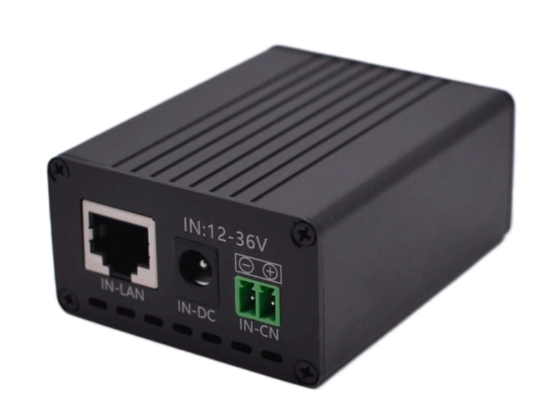
The Maxsol POE24V DC-to-PoE power converter accepts 12–36V DC and provides adjustable 12–57V PoE output, Gigabit Ethernet and an LCD voltage display. Its documented continuous load when converting 12V to 48V is no more than 30W, and the stated conversion efficiency of up to 94% is a maximum rather than a guaranteed design value.
IEEE powered-device detection or negotiation is not established by those facts. Installers must verify voltage, polarity, pinout, protocol and load compatibility before connecting a camera or radio.
Choose connectivity for a changing site
Construction-site backhaul can change even when the camera remains in place. Scaffolding, stacked materials, temporary offices, steelwork and new walls can obstruct radio paths. A connection that works during earthworks may be unsuitable once the building reaches roof height.
The main temporary options are cellular and point-to-point or point-to-multipoint wireless links. Neither is universally better.
| Selection factor | Cellular connection | Site wireless link |
|---|---|---|
| Basic dependency | Suitable mobile coverage and service | Clear or workable radio path to another network point |
| Effect of relocation | May continue if coverage remains adequate | Alignment and line of sight usually need rechecking |
| Local infrastructure | Does not require a nearby site network endpoint | Requires a base, bridge or access point |
| Obstruction sensitivity | Building materials may weaken indoor or shielded reception | New structures, cranes and stacked materials may block the path |
| Ongoing commercial terms | Confirm data plan, management and service conditions | Confirm equipment, mounting and network-management requirements |
| Best fit | Widely dispersed or frequently moving units | Sites with a stable network hub and suitable radio paths |
A cellular camera or router can simplify early deployment, but coverage must be tested at the intended mounting height and inside any proposed enclosure. Do not assume that a handheld test at ground level represents the final installation.
Wireless bridging can reduce dependence on cellular coverage where the site has a stable office, recording point or upstream network. However, the path must be surveyed again as structures rise.
The Maxsol CPE295 5.8GHz wireless CPE documents a 2x2 14dBi directional MIMO antenna, one Gigabit LAN port, IEEE 802.3af/at or 9–48V DC power support, and 6.5W full-load consumption. Product range and wireless rate labels do not guarantee site distance or application throughput. Check line of sight, mounting stability, interference, channel planning and applicable local radio requirements.
Plan for backhaul migration
A practical temporary design may use different links during different project phases. For example:
- Cellular during early works when there is no site network
- A wireless bridge once the site office and network core are operational
- A relocated bridge when a new structure blocks the original path
- Temporary local recording during a planned backhaul change
Document IP addressing, credentials, recording destinations and bandwidth requirements so that a physical relocation does not become an unplanned network redesign. If cameras record centrally, confirm how the system behaves when the backhaul drops. If they record locally, include storage health and retrieval in the maintenance plan.
Plan modular mounting and secure enclosures
Temporary does not mean lightly secured. Solar panels, batteries, radios and visible copper cabling may be exposed to theft, tampering, dust, water, impact and construction activity.
Use a modular assembly that separates functional components while allowing the complete station to move efficiently. A typical arrangement may include:
- A stable pole, weighted base or engineered temporary structure
- A camera bracket with repeatable adjustment points
- A separately adjustable solar-panel frame
- A lockable equipment enclosure
- Protected cable entries and strain relief
- Short, labelled internal power leads
- Tamper-resistant external fixings
- A bonding or earthing arrangement appropriate to the design
- Physical protection from vehicles and mobile plant
Do not attach equipment to scaffolding, fencing or temporary structures without confirming that the mounting point can carry the equipment and expected wind loading. Movement that is too small to notice visually can still disrupt a directional wireless link or alter a camera’s identification view.
Separate camera aiming from panel aiming
The best camera angle is rarely the best solar-panel orientation. Mounting both on one fixed bracket can force a compromise and make future recommissioning more difficult.
The camera should be aimed for surveillance coverage. The panel should be independently oriented for solar exposure, using true north as an initial orientation reference in South Africa and then checking the actual site’s shade profile and mounting constraints.
Protect equipment without creating new problems
An enclosure must provide appropriate environmental and impact protection while allowing safe cable entry, heat management and maintenance access. Avoid assuming that a higher protection label automatically solves condensation, impact, gland selection or thermal issues.
For a focused explanation of environmental sealing and impact resistance, use the guide to IP65 and IK10 outdoor CCTV enclosures rather than choosing solely by a single rating.
Also consider internal layout. Batteries, converters, network devices and protective components need adequate spacing, secure termination and service access. The outdoor PoE switch box, power, fibre and battery guide covers broader enclosure planning without treating the box as merely a weather cover.
Reduce theft and tampering exposure
Risk controls should not prevent legitimate maintenance. Useful measures include:
- Keeping the battery and network equipment in a locked enclosure
- Avoiding exposed, easily unplugged connectors
- Routing cables inside poles or protected conduit where practical
- Using fixings that require controlled tools
- Positioning the station outside normal vehicle paths
- Recording equipment serial numbers and configuration details
- Applying clear asset labels
- Restricting enclosure keys and network credentials
- Using the camera layout to provide overlapping observation where justified
Do not position the solar panel where it becomes an easy climbing aid to the camera or enclosure. Similarly, avoid mounting the enclosure so high that routine battery, controller or cable checks require unsafe access.
Recheck solar exposure after every relocation
Solar exposure changes throughout construction. New floors, site sheds, hoarding, cranes, stockpiles and neighbouring equipment can shade a panel that was unobstructed during the initial survey. Dust and construction residue can further reduce available charging energy.
A relocation survey should consider both current and planned structures. Check the panel over the relevant part of the day rather than judging it from a single observation.
After moving a station:
- Confirm that the mounting base and pole are stable.
- Reorient the panel and tighten its frame.
- Check for present and likely future shade.
- Inspect the panel surface for dust, concrete residue or damage.
- Confirm panel polarity before reconnecting.
- Inspect battery and controller connections.
- Verify charging status using the controller’s documented indicators.
- Observe system voltage with the full site load active.
- Recheck the camera view after final panel and radio adjustment.
- Record the new location, orientation and commissioning results.
Treat shade as a design change
Moving a station from an open perimeter to the side of a rising building is not a like-for-like relocation. Even if the camera and radio loads remain unchanged, the available charging window may be materially different.
Do not respond automatically by adding a larger panel or battery. First establish:
- Whether the panel can be moved away from the camera
- Whether a remote panel would introduce unacceptable cable loss
- Whether the load can be reduced
- Whether night lighting behaviour can be adjusted without undermining surveillance
- Whether another mounting position provides better exposure
- Whether a different backhaul method would consume less power
Any revised panel, controller or battery combination must remain within documented electrical limits. Do not infer compatibility from connector appearance or nominal voltage alone.
Commission and hand over the temporary system
Commissioning proves that the system is correctly installed at its present position. Recommissioning proves the same after each relocation or material site change. A camera appearing online is not enough.
Use a repeatable checklist covering power, video, networking, mechanical security and documentation.
Power and solar checks
- Record battery voltage and controller status.
- Confirm correct panel and battery polarity.
- Measure or verify the operating load.
- Test night mode and any auxiliary lighting.
- Check converter output voltage before attaching the powered device.
- Inspect terminals, fuses and cable strain relief.
- Confirm that no cable is pinched or exposed to sharp metal.
- Review low-voltage behaviour and recovery settings where configurable.
- Confirm that the revised load remains within every component’s limits.
Camera and network checks
- Verify the camera view in daylight and night mode.
- Confirm focus and required identification areas.
- Test recording, playback and timestamps.
- Check alert delivery where alerts form part of the design.
- Measure link stability under normal site activity.
- Confirm wireless alignment and line of sight.
- Verify cellular performance at the installed position where applicable.
- Test local recording or failover behaviour during a backhaul interruption.
- Confirm that default credentials have been replaced.
Mechanical and security checks
- Tighten mounting hardware to the installation requirements.
- Confirm that panel, camera and antenna adjustments are locked.
- Test enclosure locks and inspect cable entries.
- Check that the station does not obstruct vehicles, pedestrians or work activities.
- Confirm safe maintenance access.
- Photograph the completed installation for the handover record.
- Update the asset register and relocation schedule.
Handover information
Provide the site team with enough information to operate and move the system responsibly:
- Current equipment location and surveillance purpose
- Approved next relocation point
- Basic isolation and restart procedure
- Cleaning and inspection frequency
- Escalation process for low battery, lost video or failed backhaul
- Network addressing and authorised access details
- Camera view reference images
- Panel orientation and shade observations
- Latest load budget
- Configuration backups
- Recommissioning checklist
Make it clear that physical relocation requires technical recommissioning. Moving a pole and reconnecting the same plugs does not confirm that solar charging, camera coverage or wireless performance remains acceptable.
Common construction-site design mistakes
Avoid these recurring problems when specifying solar CCTV for construction sites:
- Sizing from camera wattage while ignoring radios, converters and night loads
- Treating nominal battery capacity as fully usable energy
- Assuming a product’s maximum efficiency is a guaranteed operating value
- Combining PoE equipment without checking voltage, polarity, pinout and protocol
- Mounting the camera, panel and directional antenna on one non-adjustable bracket
- Surveying shade only at the initial project phase
- Relying on a wireless range label instead of checking the actual path
- Testing cellular reception only at ground level
- Installing an enclosure that is difficult or unsafe to service
- Moving equipment without updating the camera view and network records
- Treating linked products as a tested compatible bundle
- Promising universal autonomy without site-specific load and charging data
A resilient temporary installation is one that can be surveyed, moved, tested and documented repeatedly. The next practical step is to compare the linked Maxsol selection examples with the project’s camera count, continuous and night loads, required distance, input and PoE requirements, environmental exposure, backhaul method and management needs. Verify current datasheets and the supplied configuration before treating any components as compatible.