IP65 and IK10 Outdoor CCTV Enclosures: Selection Guide
Understand IP65 and IK10 ratings for outdoor CCTV enclosures, then choose the right size, material, mounting and cable-entry arrangement.
By Maxsol Team

An IP65 IK10 outdoor CCTV enclosure addresses two separate risks: ingress from dust and water, and mechanical impact. IP65 indicates protection against dust and water jets, while IK10 indicates a high level of resistance to impact. Neither rating alone confirms that an enclosure will fit your equipment, manage heat well, or remain protected after cables and glands have been installed.
For a reliable outdoor CCTV installation in South Africa, specify the enclosure around the complete site requirement: camera support equipment, PoE or network hardware, power components, cable bend radius, mounting method, sun exposure, drainage, earthing and future service access. The right box is the one that retains suitable protection once it is fitted and wired—not simply the one with the highest rating on its label.
IP and IK ratings answer different questions
IP and IK ratings are often quoted together, but they measure different forms of protection.
- IP rating assesses protection against ingress of solid objects and water.
- IK rating assesses resistance to external mechanical impact.
For CCTV infrastructure, both can matter. An enclosure installed at a perimeter fence, gate, parking area or pole may be exposed to wind-driven rain, dust, cleaning activity, accidental knocks or deliberate interference. However, the ratings should be interpreted precisely.
What IP65 means for an outdoor enclosure
An IP rating has two digits. With IP65:
- The first digit, 6, means the enclosure is dust-tight under the applicable test conditions.
- The second digit, 5, means it is protected against water jets from any direction under the applicable test conditions.
IP65 does not mean an enclosure is suitable for submersion, permanent flooding, or every possible high-pressure washdown arrangement. It also does not automatically protect the system if an incorrectly sized cable gland, damaged gasket, open knockout or poorly sealed conduit entry is used.
For an outdoor CCTV enclosure, IP65 is generally relevant where the box needs protection from airborne dust and rain exposure, provided the installed cable-entry system maintains the intended protection level.
What IK10 means for an outdoor enclosure
The IK rating is based on the enclosure’s resistance to impact. IK10 is the highest commonly specified level in the IK classification and corresponds to an impact energy of 20 joules under the test standard.
An IK10 enclosure can be a practical choice where equipment is mounted within reach, near access-controlled entrances, on exposed walls, or on poles where accidental contact is possible. Still, an impact rating is not a guarantee against every attempted attack, cutting tool, vehicle strike or mounting failure. The enclosure, door, locks, hinges, fasteners and supporting surface must all be considered together.
Why IP65 and IK10 should be specified together
An enclosure may provide strong impact resistance without a suitable ingress rating, or offer water and dust protection without the same level of mechanical protection. For exposed CCTV and network equipment, an IP65 IK10 outdoor CCTV enclosure can therefore be a more meaningful starting point than either rating alone.
Check the rating for the exact enclosure configuration you intend to use. Drilling additional holes, fitting unsuitable accessories, leaving unused openings unsealed or changing the cover arrangement can affect installed protection.
Measure the equipment and cable space
The most common enclosure-selection mistake is sizing the box only around the external dimensions of a switch, power supply or battery. In practice, the required internal working space is larger than the equipment footprint.
Start with a layout of every component that will sit inside the enclosure, such as:
- PoE switch, Ethernet switch or media converter
- DC power supply, surge protection or circuit-protection components
- Fibre splice or termination hardware
- Battery or solar charge-control components, where applicable
- DIN rail, mounting plate, cable duct and terminals
- Service loops for network, power and camera cables
Allow for usable, not nominal, space
Do not assume that the stated enclosure dimensions equal clear, usable space. Door depth, mounting plates, internal rails, cable routing and minimum bend radius can all reduce available room.
A practical layout should leave enough clearance to:
- Close the door without compressing cables.
- Route cables without sharp bends or strain on connectors.
- Remove or replace a switch, fuse or power supply.
- Read labels and indicator lights during fault-finding.
- Keep mains, low-voltage DC and data cabling arranged in accordance with the installation design and applicable requirements.
Also consider the direction from which cables enter. Bottom entry is often preferred for outdoor installations because it can reduce the likelihood of water tracking along a cable into an entry point. This is not a substitute for properly rated glands, sealing and strain relief.
Compare actual enclosure sizes
The following documented options illustrate why dimensions should be matched to the equipment layout rather than chosen by rating alone.
| Enclosure | Documented dimensions | Material | Protection and impact rating | Mounting |
|---|---|---|---|---|
| IB542 | 500 × 400 × 200 mm | 1.2 mm galvanised steel with powder coating | IP65, IK10 | Wall or pole |
| IB552 | 550 × 450 × 280 mm | 1.2 mm galvanised steel with powder coating | IP65, IK10 | Wall or pole |
| IP652 | 600 × 500 × 220 mm | 4 mm ABS housing | IP65, IK09 | Confirm mounting arrangement for the planned installation |
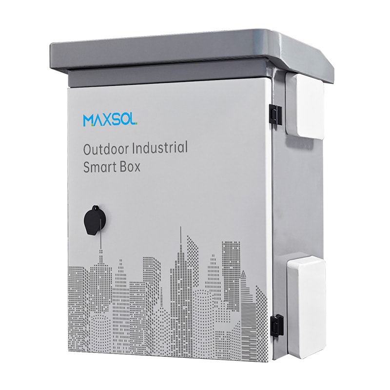
The IB542 IP65 IK10 industrial outdoor smart box measures 500 × 400 × 200 mm. It may suit a compact arrangement where a mounting plate and organised cable routing are more important than maximising empty volume.
Where greater depth and a larger overall enclosure are needed, the IB552 IP65 IK10 industrial outdoor smart box measures 550 × 450 × 280 mm. The added depth can be particularly important where plugs, power supplies, cable loops or door-mounted components project forward.
Before ordering, create a simple scaled layout or place the proposed components on a board at their actual spacing. This quickly reveals clashes between connectors, glands, door clearance and maintenance access.
Compare steel and ABS enclosure options
Material affects impact resistance, corrosion management, weight, thermal behaviour and the practical way an enclosure is installed. There is no single best material for every CCTV site.
Galvanised steel for exposed or higher-impact locations
The IB542 and IB552 are documented as 1.2 mm galvanised steel enclosures with powder coating, IP65 protection and IK10 impact resistance. Steel is often considered where a project requires a robust enclosure body and a higher impact classification.
For a steel enclosure, assess:
- Whether the mounting wall or pole can safely carry the enclosure and internal equipment.
- The condition of the coating before and after installation.
- Whether drilling, cut-outs or damaged finishes need appropriate treatment.
- The required earthing or bonding arrangement for the completed installation.
- Whether internal heat from active electronics needs additional planning.
A metal enclosure can also require more care around cable-entry hardware, especially where glands, conduit fittings, locknuts and bonding connections must work together.
ABS for corrosion-conscious and lower-impact applications
The IP652 is a 600 × 500 × 220 mm ABS enclosure with a 4 mm housing, IP65 protection and IK09 impact resistance. It is documented as suitable for junction, distribution, battery, control and monitoring uses.
An IP652 plastic distribution box can be worth considering where the equipment arrangement benefits from its stated dimensions and where IK09 is appropriate for the site’s assessed impact risk. ABS can be useful in installations where avoiding metal corrosion is a key design consideration, but it should not be assumed to provide the same impact classification as an IK10 steel option.
Material selection should also account for solar exposure. Enclosures in direct sun can become significantly warmer than ambient conditions. The colour, location, internal load and ventilation strategy all affect operating temperature. Confirm that every internal device is rated for the expected conditions; the enclosure rating does not extend the device’s own environmental limits.
Do not choose material by appearance alone
A neat enclosure installation may still be difficult to service or vulnerable to water ingress if the wrong glands, screws, seals or bracket arrangement are used. Compare the full system:
- Enclosure body and cover
- Door seal and closure arrangement
- Mounting hardware
- Glands, plugs and conduit interfaces
- Cable support and strain relief
- Internal mounting method
- Earthing, surge protection and power segregation needs
Plan wall or pole mounting
Mounting decisions affect security, water management, maintenance and cable routing. They should be made before the enclosure is drilled or populated.
The IB542 and IB552 support wall or pole mounting. Choose between these methods based on the physical site, cable routes and access requirements.
Wall mounting considerations
Wall mounting can simplify access where a secure, stable surface is available. Position the enclosure so that the door can open fully and a technician can work safely in front of it.
Check:
- The substrate type and condition.
- Fastener type, embedment and load suitability.
- Clearance from vehicle routes, gates and pedestrian traffic.
- Whether the enclosure is placed under persistent runoff from roofs, pipes or air-conditioning drain lines.
- Space for conduit bends, cable loops and service access.
Avoid mounting an enclosure where water pools behind it or where the door seal is continually exposed to concentrated runoff. A rating does not eliminate the need for sensible placement.
Pole mounting considerations
Pole mounting is common where CCTV cameras, wireless links, solar equipment or perimeter infrastructure are located away from buildings. It can shorten cable runs to the camera or radio, but it introduces additional structural and servicing considerations.
For a pole-mounted enclosure, verify:
- Pole diameter and condition.
- Bracket compatibility and fastening method.
- Wind loading on the enclosure, connected conduit and any associated equipment.
- Mounting height and safe access for maintenance.
- Potential for vibration or movement.
- Separation from areas where vehicles, ladders or public activity may strike the enclosure.
Keep the enclosure high enough to reduce casual interference and splash exposure, while still allowing safe servicing. Excessive mounting height can turn routine diagnostics into a difficult maintenance task.
Avoid obstructing the enclosure door
Whether wall- or pole-mounted, make sure cable trays, conduits, camera brackets and nearby structures do not block the door or cover fasteners. Leave enough space to inspect seals, replace glands and remove internal components without dismantling the entire installation.
Cable entry, grounding, cooling and maintenance
An enclosure’s published IP and IK ratings are only part of the installed outcome. Cable entry, electrical protection, thermal planning and maintenance often determine whether the CCTV support system stays manageable over time.
Use cable entries that preserve protection
Each cable entry needs a suitable gland, grommet, blanking plug or conduit fitting selected for the cable diameter and installation environment. An oversized hole with sealant around a cable is not a dependable substitute for a correctly selected cable-entry component.
Good practice includes:
- Use glands sized for the actual cable outer diameter.
- Seal every unused entry with an appropriate blanking solution.
- Provide strain relief so cable weight is not carried by terminals or connectors.
- Keep entries clear of standing water and avoid upward-facing openings where possible.
- Maintain cable bend radius, especially for fibre and screened data cable.
- Label cables at both ends before closing the enclosure.
If a new hole is drilled, remove swarf and check that sharp edges cannot damage insulation. On steel enclosures, also consider how the cut edge and fitting affect corrosion protection and bonding.
Plan grounding and surge protection as a system
Outdoor CCTV equipment may be connected to long copper runs, metal poles, external power supplies or exposed network cabling. Grounding, bonding and surge protection should be designed by a suitably competent installer for the site and system architecture.
A metal enclosure may require protective earthing or bonding arrangements appropriate to the equipment and installation. Do not rely on a mounting bracket, painted surface or cable screen as the only grounding path. Similarly, installing a surge-protection device is not enough unless its earth connection, conductor length and coordination with the rest of the installation are properly considered.
Confirm the requirements for the actual power source, network topology, camera equipment and local installation conditions before commissioning.
Manage internal heat and condensation
IP65 enclosures are sealed against dust and water jets, so internal heat cannot simply be ignored. PoE switches, power supplies, battery chargers and other active components generate heat, especially where cameras draw power continuously.
To reduce avoidable heat stress:
- Calculate the heat load of all internal devices.
- Check the temperature limits of each device, not only the enclosure.
- Avoid placing the enclosure in full afternoon sun where another location is viable.
- Maintain clearance around equipment for natural internal air movement.
- Avoid overfilling the box with tight cable bundles.
- Assess whether a suitably engineered cooling or thermal-management approach is required.
Adding vents or fans without considering ingress protection can compromise the original enclosure performance. If cooling is required, confirm the resulting protection level of the complete assembled design.
Condensation can also occur as temperatures change. Cable entry, installation orientation, internal load and site conditions all influence moisture behaviour. Inspect seals and glands periodically rather than assuming a closed enclosure remains unchanged indefinitely.
Make maintenance possible
CCTV projects are easier to support when the enclosure is organised from day one. Leave a current wiring diagram or clear circuit identification inside the door where appropriate, label ports and power feeds, and record the purpose of each cable.
During periodic inspection, check for:
- Damaged door seals, hinges, locks or closures.
- Loose mounting hardware.
- Cracked glands, unsealed entries or deteriorated conduit fittings.
- Water marks, dust accumulation or corrosion.
- Cable strain and connector damage.
- Heat discolouration, unusual odours or failed power components.
- Clear labels and readable service information.
Selection checklist
Use this checklist when comparing an IP65 IK10 outdoor CCTV enclosure for a new or replacement installation.
- Define the environmental exposure. Is the enclosure exposed to dust, rain, water jets, direct sun, coastal air, vehicle movement or public access?
- Separate ingress and impact requirements. Specify IP protection for dust and water exposure, and IK protection for the assessed physical-risk level.
- List every internal component. Include switch, injector, power supply, protection devices, terminals, fibre hardware, batteries and mounting accessories.
- Allow installation clearance. Make room for cable bend radius, glands, connector depth, door closure and technician access.
- Choose material for the location. Compare galvanised steel and ABS based on impact needs, corrosion considerations, mounting load and thermal planning.
- Confirm mounting details. Check wall or pole dimensions, bracket arrangement, load support, access height and door clearance.
- Specify cable entries early. Select the correct gland types, sizes, blanking plugs and strain-relief approach before drilling.
- Plan grounding and surge protection. Treat these as system-level design items, particularly for outdoor copper runs and metal structures.
- Check thermal conditions. Consider total device power, sun exposure, expected ambient temperature and the limits of internal equipment.
- Plan servicing. Ensure technicians can open the enclosure, isolate equipment, inspect seals and replace components without disturbing the whole installation.
The best next step is to compare the IB542, IB552 and IP652 options against your required port count, electrical load, cable distance, power design, environment and management requirements before finalising the enclosure layout.