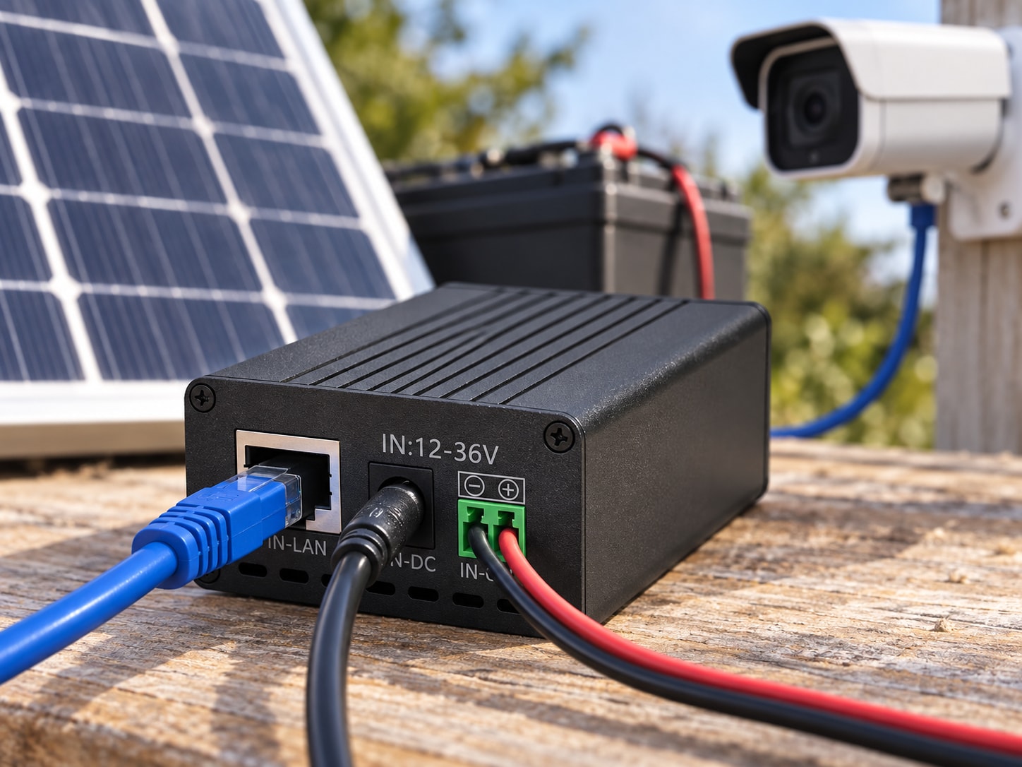
Designing Off-Grid Power for Outdoor PoE Cameras
Learn how to size solar, battery and DC-to-PoE equipment for outdoor cameras, including cable loss, backhaul, compatibility and safe restarts.
By Maxsol Team

To power outdoor PoE cameras without grid electricity, use a solar panel, MPPT charge controller and battery to create a stable DC supply, then feed the camera through a compatible DC-to-PoE converter or solar PoE switch. Ethernet carries the camera data to a recorder or wireless backhaul independently of the solar charging path.
A reliable design requires two separate calculations. First, confirm that the solar array and battery can support the full daily energy demand during the site’s least favourable solar month. Second, verify that the PoE source and camera are electrically compatible in voltage, protocol, polarity, pinout, power capacity and cable distance. Passing one check does not mean the other will pass.
Map the solar energy and Ethernet data paths
An off-grid camera site has two connected but distinct paths: the energy path and the data path.
Solar energy path
A typical single-site power path is:
- Solar panel: Converts sunlight into DC electricity.
- MPPT charge controller: Regulates panel output and charges the battery according to the battery’s required profile.
- Battery: Stores energy for night-time operation, cloudy periods and temporary demand peaks.
- DC protection and distribution: Fuses, breakers and correctly sized conductors distribute battery power safely.
- DC converter or PoE power source: Produces the voltage and pinout required at the Ethernet port.
- Outdoor PoE camera: Receives power and data through its Ethernet interface.
Keeping the system DC-coupled normally avoids the extra conversion stages involved in changing battery DC to AC and then back to DC at a conventional PoE injector. Fewer conversion stages can reduce losses, but only when every device accepts the available DC voltage and the complete arrangement is properly protected.
Ethernet data path
The data route may be:
Camera → PoE converter or switch → network switch, router or recorder
For a remote installation, it may instead be:
Camera → PoE device → wireless CPE bridge or cellular router → remote monitoring point
The backhaul equipment is also an electrical load. Include its radio, router, network switch, storage equipment and any enclosure controls in the energy calculation if they operate from the same solar system.
A more detailed overview of these building blocks is available in this guide to solar power for off-grid PoE networking.
Measure camera and auxiliary power demand
Do not size the system from the camera’s headline wattage alone. Measure or confirm the power demand of every device and consider how that demand changes after dark, during boot-up and when optional camera functions activate.
Typical loads to include are:
- PoE cameras
- Infrared illuminators
- Pan-tilt-zoom motors
- Heaters, blowers or demisters
- Network switches or injectors
- Wireless bridges and access points
- Cellular routers
- Local recorders or edge computers
- Enclosure fans or thermostats
- Monitoring relays and control electronics
- DC conversion losses
Calculate daily energy, not only instantaneous watts
For each load:
Daily energy in Wh = operating watts × hours per day
If a camera averages 12 W over 24 hours:
12 W × 24 h = 288 Wh per day
If a backhaul radio uses 8 W continuously:
8 W × 24 h = 192 Wh per day
These two loads already require 480 Wh per day before allowing for the PoE converter, controller consumption, cable loss, battery losses or other equipment.
For devices with variable demand, break the calculation into operating states. For example:
- Day mode: watts × daylight operating hours
- Night mode with infrared: watts × night operating hours
- PTZ movement: additional watts × estimated movement time
- Startup: peak watts and duration
Use measured consumption where possible. A nameplate maximum is useful for electrical compatibility and peak-load checks, while an actual 24-hour power log is more useful for energy sizing.
Account for night-time load
Outdoor surveillance systems often draw more power at night because infrared LEDs activate. At the same time, the solar panel has stopped producing energy, so the battery must carry the full load.
Test the camera in darkness rather than assuming its daytime reading represents continuous consumption. If the design includes multiple cameras, trigger their night functions together to reveal the combined demand.
Allow for startup and inrush demand
A converter may support the normal running load but still shut down when several devices restart simultaneously. Cameras, radios and infrared arrays can briefly demand more power while booting.
Check:
- Converter peak and continuous output limits
- Battery voltage drop during startup
- Low-voltage cut-off behaviour
- Simultaneous camera and radio boot demand
- Repeated restart cycles after a low-battery event
A safe design should start cleanly at the lowest expected operating battery voltage, not only when the battery is fully charged.
Size storage and array for the design month
Solar sizing should use the site’s least favourable practical month, not an annual average or the best summer conditions. South African solar conditions vary considerably by location, season, panel orientation, local shading and weather pattern.
Obtain credible site-specific peak-sun-hour data, then apply realistic system losses. Check for nearby trees, masts, buildings, terrain and the camera pole itself casting shadows across the panel.
Size the battery for usable energy
Battery nameplate energy is:
Nominal battery energy in Wh = nominal voltage × amp-hour capacity
Usable energy will be lower after considering:
- Permitted depth of discharge
- Battery management system cut-off
- Temperature effects
- Battery ageing allowance
- DC conversion losses
- Cable losses
- A reserve for poor solar conditions
- The minimum voltage required by downstream equipment
A basic storage calculation is:
Required nominal storage = daily load × autonomy days ÷ usable battery fraction
Do not treat the result as the final battery specification until voltage limits, startup current and the battery’s supported charge and discharge conditions have also been checked.
The Maxsol CS12060 120 W and 768 Wh solar system is one architecture example. Its documented components include a 120 W monocrystalline panel, MPPT controller, 12.8 V 60 Ah LiFePO4 battery rated at 768 Wh and three DC 12 V outputs.
Those figures do not establish a universal camera runtime. Actual runtime depends on the usable battery window, total connected load, conversion efficiency, cable loss, temperature and battery condition. The 120 W panel must also be evaluated against the site’s design-month solar resource and daily energy requirement.
Size the array from daily replacement energy
A simplified starting point is:
Required panel watts = daily load in Wh ÷ design peak-sun-hours ÷ overall charging factor
The overall factor must account for real losses and operating conditions, including:
- Panel temperature
- Dust and soiling
- Cable voltage drop
- MPPT and charging losses
- Battery charging efficiency
- Panel angle and orientation
- Partial shading
- Seasonal weather
- A recovery margin after a low-solar period
An array should do more than maintain the load on a perfect day. It should normally have enough margin to operate the equipment while restoring battery charge after overnight use.
For a structured calculation process, see how to size an off-grid solar power system for CCTV.
Capacity and charging rate are separate checks
A larger battery provides more stored energy, but it also takes longer to recharge from a given array. Increasing battery capacity without reviewing panel size can leave the system chronically undercharged during the design month.
Conversely, a large panel does not compensate for insufficient night-time storage. Confirm both:
- Battery capacity: Can it support the load for the required night and autonomy period?
- Solar recovery: Can the array replace the consumed energy within the available solar window?
Verify converter voltage, polarity, pinout and protocol
“PoE” does not describe one universally interchangeable electrical output. A camera may expect standards-based IEEE PoE negotiation, or it may accept passive power on specified pairs at a fixed voltage.
Before connecting equipment, verify all of the following:
| Compatibility check | What to confirm |
|---|---|
| Camera input | Accepted PoE standard or passive DC range |
| Negotiation | Whether powered-device detection and classification are required |
| Output voltage | Voltage permitted at the camera port |
| Polarity | Positive and negative assignment |
| Pinout | Which Ethernet pairs carry power |
| Power capacity | Continuous and startup watts required by the camera |
| Converter input | Full battery voltage range, including charge and cut-off conditions |
| Cable loss | Voltage and power available at the far end |
| Data rate | Ethernet speed required by the camera and backhaul |
| Connector use | Shielding, earthing and weatherproofing requirements |
An adjustable output voltage does not by itself make a converter IEEE 802.3af, 802.3at or 802.3bt compliant. Standards-based PoE normally involves detection and electrical behaviour beyond simply presenting a selected voltage on Ethernet conductors.
The Maxsol POE24V DC-to-PoE converter accepts a documented 12–36 V DC input and provides an adjustable 12–57 V PoE output, Gigabit Ethernet and an LCD voltage display. Its documented continuous load when converting from 12 V to 48 V is at most 30 W.
Its published conversion efficiency of up to 94% is a maximum, not a guaranteed design value for every input voltage and load. IEEE powered-device detection or negotiation is not established by the supplied product facts. Confirm the intended camera’s voltage, protocol, polarity, pinout, demand and cable loss before connection.
The CS12060 and POE24V illustrate possible stages in an architecture, but they should not be treated as a tested compatible bundle.
Calculate cable voltage drop
Long copper runs create resistance, reducing the voltage available at the camera and increasing the power drawn at the source. The effect becomes more important with:
- Higher camera power
- Lower PoE voltage
- Longer cable
- Smaller conductor size
- Poor-quality connectors
- Elevated cable temperature
Do not check only whether the link passes Ethernet data. A camera may establish a network connection during the day and reset at night when infrared demand raises the current and cable loss.
Conventional copper Ethernet links are generally designed around a maximum 100 m channel, but a power budget may impose a shorter practical distance. For longer links, consider relocating the power source, using fibre with remote power, or adding an intermediate network architecture rather than exceeding the equipment and cabling limits.
Include backhaul, monitoring and restart loads
A remote camera is only useful if its data path remains available. Include the backhaul in both the network design and the energy budget.
Select the backhaul path
Common options include:
- Point-to-point wireless bridge
- Point-to-multipoint wireless network
- Cellular router
- Fibre where a suitable route exists
- Local recording with periodic remote access
Check bandwidth in both directions, particularly where several cameras share one uplink. Camera bitrate, frame rate, resolution, compression, event uploads and remote playback can all affect the required capacity.
Wireless links need a suitable path and alignment. Also account for the radio’s continuous power demand, not just the cameras.
Monitor the energy system
Useful remote measurements include:
- Battery voltage
- Battery state of charge, where reliably supported
- Charge and load current
- Solar charging state
- Low-voltage alarms
- Camera and backhaul reachability
- Enclosure temperature
- Restart history
Voltage alone can be an imperfect measure of LiFePO4 state of charge because its operating voltage remains relatively flat through much of the discharge cycle. Use available battery-management or charge-controller information where practical.
Design predictable restart behaviour
After an extended low-solar period, the battery protection system or controller may disconnect the load. If everything restarts as soon as voltage rises slightly, the combined boot demand can pull the voltage down again, creating a repeated on-off cycle.
Reduce this risk with:
- Suitable low-voltage disconnect thresholds
- Adequate reconnect hysteresis
- A time delay before reconnecting loads
- Sequential startup of radios and cameras
- A minimum battery recovery level before restart
- Watchdog logic that does not cause uncontrolled reset loops
- Retained device configuration after complete power loss
Decide which load should return first. In some designs, the backhaul should start before the cameras so that the site can report its status. In others, a local recorder or priority camera may need to come online first.
Outdoor protection also matters. Specify suitable enclosures, cable glands, strain relief, fusing, surge protection and earthing for the site. Lightning exposure, coastal corrosion, heat and dust should be assessed according to the installation environment rather than assumed from the camera’s enclosure rating alone.
Bench-test and commission before remote deployment
Build and test the complete arrangement before installing it at a difficult-to-access site. A bench test should use the actual camera, converter, cable length, backhaul hardware, battery voltage range and planned configuration.
Recommended bench-test sequence
- Record every load: Measure daytime, night-time and startup demand.
- Confirm DC polarity: Check battery, controller and converter connections with a meter.
- Set the output before connecting the camera: Verify voltage and pinout without relying only on a display.
- Confirm PoE behaviour: Establish whether the camera requires IEEE negotiation or accepts the proposed passive arrangement.
- Use the planned cable: Test with the same cable type and approximate length intended for site use.
- Force night mode: Activate infrared illumination and other night functions.
- Restart all equipment together: Observe battery voltage and converter stability.
- Test at low input voltage: Reproduce the lower end of the intended battery operating range.
- Interrupt charging: Confirm expected battery-only operation.
- Simulate low-voltage shutdown: Verify that the system disconnects and restarts safely.
- Load the backhaul: Test live viewing, recording and remote access under realistic traffic.
- Inspect temperatures: Check connectors, conductors and electronics for unexpected heating.
Commissioning checks at the site
Once installed:
- Confirm panel orientation and absence of recurring shade
- Verify charging current under suitable sunlight
- Measure voltage at the battery, converter input and camera end
- Seal outdoor connectors without trapping water
- Label fuses, polarity and disconnect points
- Record converter settings
- Confirm wireless alignment or cellular signal quality
- Test remote monitoring and alarm delivery
- Capture a baseline 24-hour energy profile
- Recheck performance after several normal day-night cycles
Do not declare the site reliable based only on a sunny daytime test. Night load, poor-weather recovery and low-battery restart behaviour are often where marginal systems fail.
Common design mistakes to avoid
The most frequent errors are architectural rather than product-specific:
- Sizing from panel watts without calculating daily Wh
- Using annual-average sunshine instead of the design month
- Ignoring infrared, PTZ or heater demand
- Treating total battery capacity as fully usable
- Assuming adjustable voltage means IEEE PoE compliance
- Omitting converter and cable losses
- Forgetting the wireless or cellular backhaul load
- Using camera nameplate demand as an energy average
- Failing to test simultaneous startup
- Increasing battery capacity without checking solar recovery
- Testing with a short patch lead instead of the intended outdoor cable
- Treating two individually suitable products as a validated system
- Assuming one runtime figure applies to every site
Final selection checklist
Before procuring an off-grid camera power system, document:
- Total continuous and peak watts
- Daily energy consumption in Wh
- Required autonomy
- Design-month solar resource
- Battery chemistry, voltage and usable energy
- Array wattage and expected recovery time
- Controller and battery voltage limits
- Camera PoE protocol, voltage, polarity and pinout
- Converter continuous and startup capacity
- Cable length, conductor size and voltage drop
- Camera port count and network bandwidth
- Backhaul technology and power demand
- Monitoring and remote-reset requirements
- Enclosure, temperature, dust, moisture, corrosion and surge conditions
The practical next step is to compare the linked Maxsol models with the project’s actual port count, measured load, cable distance, power range, environment and management requirements. Treat them as individual architecture options until bench testing confirms that the complete camera, converter, solar and backhaul arrangement works safely together.