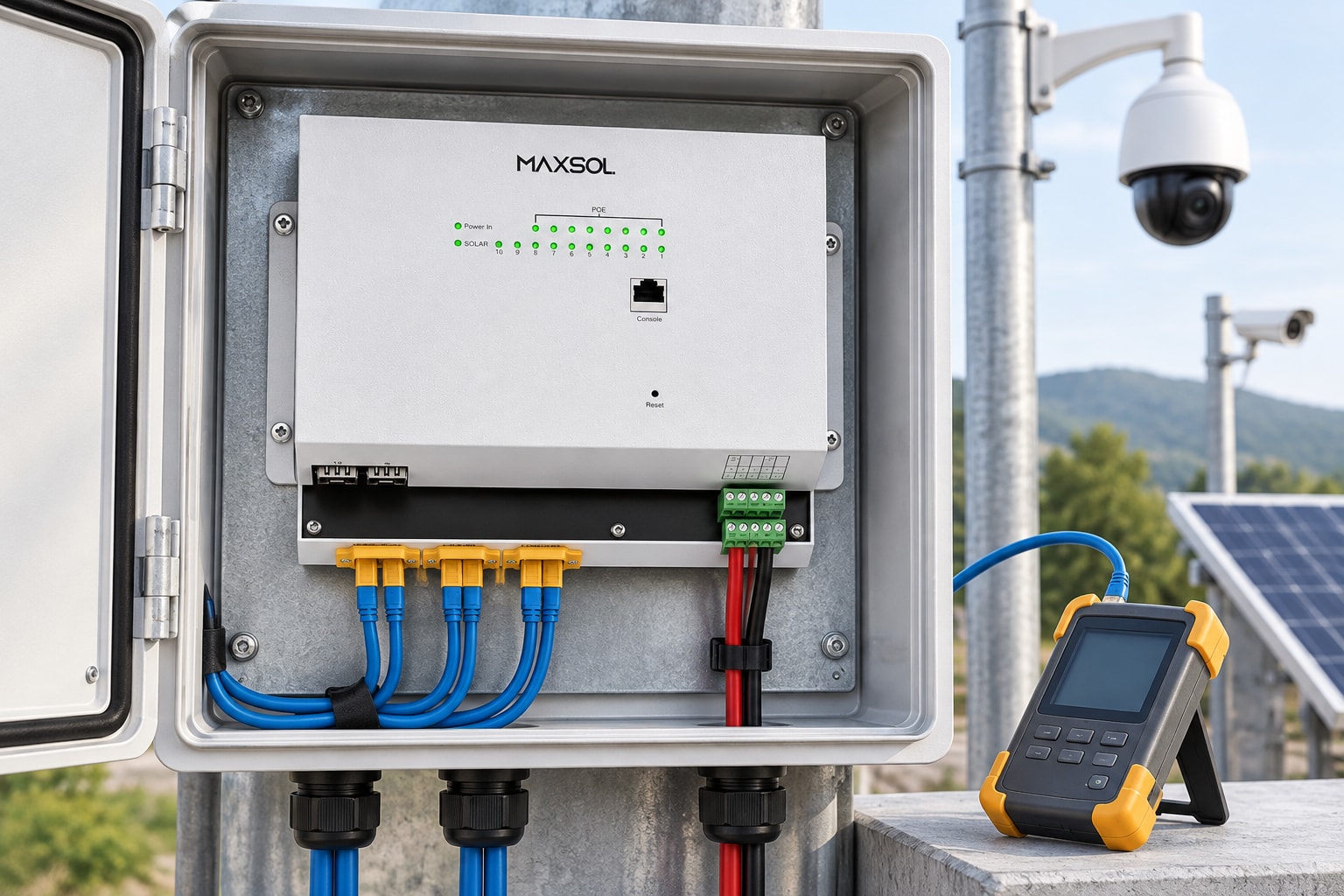
Outdoor PoE Power Checklist for CCTV Installers
Plan reliable outdoor PoE for CCTV by checking source voltage, load budget, cable loss, surge protection, enclosures, uplinks and commissioning.
By Maxsol Team

A reliable outdoor PoE installation starts with more than counting cameras and switch ports. Installers must trace the full power path—from the grid, photovoltaic array or battery through conversion and protection to each powered device—while checking voltage, load demand, cable loss, environmental exposure, uplinks and recovery after a fault.
Use this outdoor PoE power installer system integrator checklist before procurement, during bench testing and again at commissioning. Record every assumption and confirm it against current equipment datasheets; a compatible connector or matching nominal voltage does not prove that two devices can operate safely together.
Map power sources, loads, converters and interfaces
Draw a simple system diagram before selecting equipment. It should show every source, converter, switch, protection device, cable run and load. This is especially important at remote sites where DC equipment, batteries and solar controllers may use different voltage ranges or grounding arrangements.
Start by recording:
- Available power source: utility AC, generator, battery, photovoltaic system or a combination.
- Source voltage range, not only its nominal value.
- Expected interruptions, restart behaviour and backup requirement.
- Every powered load, including cameras, radios, access points, heaters and auxiliary devices.
- The voltage and power required by each load.
- All AC-to-DC, DC-to-DC and DC-to-PoE conversion stages.
- Ethernet, fibre and wireless interfaces.
- Connector type, polarity and PoE pinout.
- Protection and isolation points.
- Enclosure, cabinet and mounting arrangement.
Grid-fed integrated equipment
An integrated outdoor box can reduce the number of separate components when AC power is available at the installation point. The SBOX2802SFG-I industrial smart Ethernet box combines an IP65 enclosure, eight Gigabit PoE ports, two Gigabit SFP slots, Layer 2 management, AC100–240V input and a built-in 240W DC55V UPS module.
That combination may simplify a grid-fed CCTV node, but it does not remove the need to check:
- The PoE requirement of each connected device.
- The usable total power budget under the intended operating conditions.
- Backup duration for the actual load.
- Battery condition and replacement procedure.
- SFP module and fibre compatibility.
- Earthing, surge protection and upstream isolation.
- Cable entry sealing and installation environment.
The IP65 designation is relevant to enclosure protection, but it should not be interpreted as permission to install the unit in any exposed position. Mounting orientation, glands, unused openings, direct sun, flooding risk and service access still matter.
Solar-oriented DC equipment
A solar or battery-fed site has a different power chain. Rather than starting with AC, the design must account for the photovoltaic array, charging controls, battery operating range, DC cabling and conversion efficiency.
The IOT2802SFG-S managed solar industrial PoE switch documents eight Gigabit PoE ports, two SFP ports, a 120W PoE budget, 90W BT support, photovoltaic and battery monitoring, and photovoltaic and battery input at DC22–29.2V. It also documents configurable 24V or 48V PoE on ports 3–4.
Those details make it an example of a solar-oriented design layer, not proof that it is compatible with every panel, battery, camera or radio. Confirm the intended battery chemistry and voltage window, charging arrangement, PoE mode, pinout, polarity and load profile.
For more help choosing the system voltage, see the guide to 12V, 24V and 48V solar power for surveillance.
Stand-alone DC-to-PoE conversion
A converter may be useful when a site has an existing DC source but the network device requires a different PoE voltage. The POE24V adjustable DC-to-PoE converter accepts 12–36V DC and provides adjustable 12–57V PoE output, Gigabit Ethernet and an LCD voltage display. Its documented continuous load for 12V-to-48V conversion is no more than 30W.
Do not assume that adjustable voltage means automatic IEEE PoE negotiation. IEEE negotiation is not established by the supplied converter facts. Before connecting a powered device, verify:
- Input voltage range under charge, discharge and transient conditions.
- Required output voltage.
- Maximum continuous load at the selected conversion ratio.
- Polarity and Ethernet pinout.
- Whether the load expects negotiated IEEE PoE or a fixed passive supply.
- Inrush current and startup behaviour.
- Branch fuse or breaker rating.
- Thermal conditions inside the enclosure.
The integrated AC box, solar PoE switch and DC converter illustrate different design approaches. They are not presented as a tested compatible system.
Check per-port demand, total budget and voltage drop
A port count does not equal a power budget. An eight-port switch may have enough physical connections but insufficient total power for eight devices operating at their maximum demand.
Create a load schedule with one line per device:
| Check | What to record | Why it matters |
|---|---|---|
| Normal power | Typical operating demand | Helps estimate routine energy use |
| Maximum power | Highest documented demand | Determines port and system sizing |
| Startup demand | Inrush or boot requirement | Prevents failed or repeated restarts |
| Operating voltage | Required input or PoE mode | Avoids electrical incompatibility |
| Cable length | Full permanent-link distance | Affects voltage drop and data margin |
| Environmental load | Heater, blower or infrared operation | May raise demand at night or in cold weather |
| Criticality | Essential or non-essential load | Supports backup and load-shedding priorities |
Add the maximum demand of all devices expected to run simultaneously. Compare the result with both the switch’s total PoE budget and any individual port limitation. Leave design margin rather than treating the published ceiling as the routine operating target.
Calculate the entire energy path
For an AC-backed installation, include the switch, PoE loads, uplink equipment and backup losses. For a solar site, calculate daily energy demand as well as instantaneous power.
The energy model should account for:
- Day and night operating hours.
- Infrared illumination or other changing camera loads.
- Wireless radios changing transmit demand.
- Conversion losses at each stage.
- Switch and monitoring-system consumption.
- Battery charging and discharging losses.
- Reduced solar input during poor weather.
- Battery reserve needed for the project’s required autonomy.
Do not size a battery or photovoltaic array from the switch’s PoE budget alone. The budget is a power limit, while an off-grid design also needs an energy calculation over time.
Check DC and Ethernet cable loss
Low-voltage DC feeder loss can become significant over distance. Calculate voltage drop using the actual conductor size, route length, current and expected operating voltage. Remember that the circuit length includes the outward and return path.
Measure or calculate:
- Minimum source voltage at the worst expected battery state.
- Current at maximum simultaneous load.
- Voltage drop along the DC feeder.
- Converter input voltage after the calculated drop.
- PoE output and voltage at the remote load under operating conditions.
Long outdoor Ethernet links also require attention to cable construction, termination quality and PoE current. Use cable intended for the environment and installation method. Confirm conductor material and size rather than relying only on a category label. Copper-clad aluminium and undersized conductors can create additional loss and heating.
Specify enclosure, thermal, moisture and surge controls
An outdoor enclosure must protect equipment without trapping damaging heat or condensation. The correct design depends on exposure, solar loading, rainfall, humidity, dust, wind-driven water, insects and the heat produced by the installed devices.
Check the following:
- Enclosure ingress rating and any installation conditions attached to it.
- Resistance of the enclosure material to the intended environment.
- Direct-sun exposure and whether shading is required.
- Internal heat from switches, power supplies and converters.
- Minimum and maximum equipment operating temperatures.
- Cable-gland type, size and sealing range.
- Drip loops on external cables.
- Sealing of unused entries.
- Condensation control and pressure equalisation where appropriate.
- Separation of mains, DC power and data wiring.
- Space for bend radius, terminations, labels and maintenance.
- Safe access without disturbing live or critical circuits.
An enclosure’s rating applies to the assembled installation only when doors, seals, glands and blanking plugs are correctly fitted. Drilling an unplanned cable entry or using the wrong gland can undermine the enclosure design.
Coordinate surge, branch and overcurrent protection
Outdoor copper cables can introduce surge energy into network and power equipment. Protection should be designed as a coordinated system rather than added as a single device beside the switch.
Review protection at:
- The incoming AC supply.
- The photovoltaic array or charge-controller input.
- Battery conductors.
- DC feeders.
- Individual branches where a fault could exceed conductor or equipment limits.
- Outdoor copper Ethernet lines.
- Antenna or radio-related conductors where applicable.
Select protective devices for the circuit voltage, current, earthing arrangement and expected fault conditions. Follow applicable project requirements and the manufacturers’ installation instructions; do not copy a protection value from a different system.
Branch protection should allow a faulty camera, converter or cable to be isolated without unnecessarily shutting down the whole site. Position protection close enough to the energy source to protect downstream conductors.
Establish an intentional grounding plan
Do not treat grounding as a final cabinet connection. Record how the enclosure, mounting structure, equipment earth terminals, surge devices, cable screens and site earth system are intended to relate to one another.
Avoid improvised connections that can create unwanted circulating currents or leave a surge protector without an effective discharge path. Where electrical and lightning-protection design falls outside the installer’s scope, obtain input from the appropriately qualified project professional.
Plan uplinks, monitoring and service isolation
The power system is only useful if the site can transport video and management traffic reliably. Decide early whether the uplink will use copper Ethernet, fibre or wireless.
Fibre can provide electrical separation between remote network nodes, but compatibility still needs to be checked. Confirm:
- SFP form factor and supported module type.
- Fibre type and strand count.
- Connector type and optical budget.
- Link speed and configuration.
- Patch lead and splice arrangement.
- Availability of spare fibres.
- Module operating environment.
- How link faults will be diagnosed.
A wireless uplink needs its own power allocation, mounting plan, alignment procedure, interference assessment and recovery process.
The broader outdoor PoE switch, power, fibre and battery guide explains how these design layers fit together.
Decide what must be monitored
Managed equipment can expose useful status information, but the project should define what information operators actually need. Possible monitoring points include:
- Uplink status.
- Port status and traffic.
- PoE state.
- Device restart events.
- Battery and photovoltaic readings where supported.
- Cabinet temperature if suitable sensing is included.
- Loss of AC or DC source.
- Low-voltage alarms.
- Communication failure.
Confirm the monitoring method, management access, alarm destination and cybersecurity requirements from current documentation. Do not assume that two devices using terms such as “managed”, “smart” or “monitoring” support the same protocol or management platform.
Design for safe maintenance
Provide a clear way to isolate equipment for service. A technician should be able to identify and disconnect the relevant source without guessing which cable is live.
The plan should identify:
- Main incoming isolation.
- Battery isolation.
- Photovoltaic isolation.
- Individual DC or PoE branches.
- Separate supplies that could back-feed a circuit.
- Stored-energy hazards.
- Lock-out or access-control requirements.
- Safe test points.
- The restart sequence after maintenance.
Label conductors at both ends. If ports have special settings—such as a selected PoE voltage—mark the port, cable and connected device so that a replacement is not plugged into an unsuitable output.
Bench-test startup, faults and recovery
Bench testing should reproduce the intended configuration before equipment is installed at height, on a pole or at a remote site. Use the actual device types where practical, together with representative cable lengths and the planned power chain.
A useful bench-test sequence is:
- Inspect model numbers, connectors, polarity and labels.
- Confirm input and output settings before connecting loads.
- Power the system with no PoE devices attached.
- Record idle voltage and startup behaviour.
- Connect one load at a time.
- Confirm each port’s configuration and delivered operation.
- Apply the expected simultaneous load.
- Check conductors, connectors and converters for abnormal heating.
- Start high-demand functions such as infrared illumination where relevant.
- Confirm uplink operation and management access.
- Remove and restore the primary source.
- Observe backup transfer and recovery.
- Simulate a branch fault using an approved test method.
- Confirm that isolation works as designed.
- Restore the system and verify that all critical devices reconnect.
Test worst-case voltage conditions
A DC system should be tested or assessed at both the high and low ends of its expected source range. A battery does not remain at one nominal voltage, and a charging system may raise the bus voltage above its resting level.
Verify that:
- Every input remains within its documented range.
- The selected PoE output does not change unexpectedly after restart.
- Loads boot when source voltage is low.
- No converter is overloaded at maximum conversion demand.
- A low-voltage shutdown does not cause rapid cycling.
- The system recovers predictably when power returns.
For configurable outputs, record the exact setting and confirm it with a suitable instrument before attaching equipment. Never use a powered device as the first indication that polarity or voltage is correct.
Introduce faults one at a time
Controlled fault testing helps expose dependencies that are hidden during normal operation. Depending on the approved site procedure, test:
- Loss of AC input.
- Battery disconnection.
- Loss of photovoltaic input.
- One failed PoE branch.
- Uplink removal and restoration.
- Reboot of the switch.
- Reboot of a powered device.
- Recovery after a fully depleted backup system.
- Loss of remote management.
The objective is not only to see whether equipment restarts, but also whether it returns to the intended configuration and whether operators receive enough information to diagnose the event.
Record commissioning evidence for handover
A completed installation needs evidence, not only a statement that the cameras were online. Good records reduce future troubleshooting time and help prevent unsafe substitutions.
Include the following in the handover pack:
- Final system diagram.
- Equipment manufacturer, model and serial details.
- Current datasheets used for design.
- Source and operating voltage measurements.
- Battery and photovoltaic design assumptions where applicable.
- Load schedule and total PoE calculation.
- Port-by-port device allocation.
- Configured PoE voltage or mode for relevant ports.
- Cable type, route, length and identifier.
- Fibre and SFP details.
- Protection-device schedule.
- Earthing and bonding record.
- Enclosure entry and sealing inspection.
- Switch configuration backup.
- Management addresses and approved access procedure.
- Alarm and monitoring setup.
- Startup, shutdown and recovery sequence.
- Commissioning test results.
- Photographs of cabinet wiring, labels and terminations.
- List of unresolved limitations or deviations.
Record actual measured values alongside design values. If the measured voltage, load or temperature differs materially from the design assumption, resolve the cause rather than simply updating the paperwork.
Common outdoor PoE specification mistakes
Before signing off a design, check that the team has not:
- Selected a switch by port count while ignoring its total PoE budget.
- Treated nominal battery voltage as a fixed supply voltage.
- Assumed all equipment labelled “PoE” uses the same voltage, pinout or negotiation method.
- Ignored converter power limits at the intended input and output voltages.
- Sized solar generation from watts alone without calculating daily energy.
- Used indoor cable, glands or connectors outdoors.
- Installed surge protection without a suitable grounding path.
- Mixed power, data and fibre components without confirming interface compatibility.
- Forgotten the power demand of uplink radios and monitoring devices.
- Placed equipment in direct sun without assessing internal temperature.
- Provided no branch isolation for fault-finding.
- Failed to test restart behaviour after complete power loss.
- Left configurable PoE ports unlabelled.
- Handed over the site without configuration files and measured results.
The final selection should be based on port count, per-device and total load, cable distance, source voltage range, backup requirement, enclosure environment, uplink type and management needs. As a practical next step, compare those project requirements with the current datasheets for the SBOX2802SFG-I, IOT2802SFG-S and POE24V, then verify voltage, polarity, pinout, protocol, protection and configuration before installation.