12V vs 24V vs 48V Outdoor PoE DC Power Guide
Compare 12V, 24V and 48V DC for outdoor PoE networks, with practical guidance on voltage drop, startup sag, protection and commissioning.
By Maxsol Team

For most outdoor PoE networks, 48V DC is the practical choice for longer cable runs or higher loads because it carries the same power at a lower current than 12V or 24V. Lower current means less voltage drop, less cable heating and smaller losses. A 24V system can be a sensible middle ground, while 12V is generally best kept to short, low-power branches or equipment designed specifically for a 12V supply.
The correct decision is not based on nominal voltage alone. Compare the source’s full operating range, cable loss, startup behaviour, converter limits and every load’s permitted input range. Also remember that a 48V distribution bus is not automatically a standards-compliant PoE output: voltage, polarity, pinout and PoE detection or negotiation must all be verified.
| DC distribution voltage | Usually suits | Main advantage | Main limitation |
|---|---|---|---|
| 12V | Short runs and modest loads with native 12V inputs | Simple integration with many small battery systems | High current and proportionally large voltage drop |
| 24V | Medium-distance runs, wireless equipment and systems designed around a 24V bus | Lower current than 12V without moving the entire system to 48V | May still need conversion for conventional PoE devices |
| 48V | Longer runs, larger aggregate loads and many PoE applications | Lowest current and cable loss of the three options | Requires careful compatibility checks with batteries, controllers and non-PoE loads |
Map sources, loads and voltage ranges
Begin with a power-path diagram rather than choosing a voltage from a product label. A typical solar surveillance site may include:
- PV module and solar charge controller
- Battery and battery protection
- Main DC disconnect
- Protected DC distribution branches
- DC-to-DC or DC-to-PoE converters
- PoE switch, wireless bridge, cameras and auxiliary equipment
For each item, record:
- nominal voltage;
- minimum continuous operating voltage;
- maximum continuous operating voltage;
- startup or inrush current;
- normal and peak power;
- output regulation limits;
- undervoltage shutdown and restart thresholds;
- connector polarity and pinout;
- PoE protocol or detection requirements.
Nominal voltage is only a system label. A battery described as 12V, 24V or 48V operates across a changing voltage range as it charges and discharges. Its charge controller may also apply voltages above the nominal value. A converter must tolerate the highest possible input voltage while continuing to operate at the lowest expected input voltage.
The same distinction applies at the load. Some outdoor networking devices accept a broad DC range, while others require a tightly regulated input. A device marked “48V” should not be assumed to accept every voltage associated with a nominal 48V battery bank.
Keep the DC bus and PoE interface separate
A 24V or 48V DC cable feeding an enclosure is the distribution layer. PoE is the interface between power-sourcing equipment and the powered device over Ethernet cabling. The two may have similar voltage labels without being electrically interchangeable.
Confirm all of the following before connecting a camera, access point or bridge:
- whether IEEE PoE detection and negotiation are required;
- the permitted powered-device voltage;
- pair allocation and pinout;
- polarity;
- per-port power demand;
- total switch PoE budget.
For a fuller treatment of port demand, diversity and switch headroom, use the guide to calculating a PoE power budget for security cameras. That calculation should be completed before the DC distribution system is sized.
A 12V solar source example
The Maxsol CS12060 120W, 60Ah solar power system documents a 120W monocrystalline panel, a 12.8V 60Ah 768Wh LiFePO4 battery, an MPPT controller and three DC12V outputs, with RS485 listed as optional.
Those figures establish its nominal architecture, not guaranteed runtime or delivered energy. The stated 768Wh is nominal battery energy; usable energy at the PoE device will be lower after reserve limits, cable loss, conversion loss, temperature effects and controller consumption. Confirm the current product data for PV limits, charging temperatures, protection and controller configuration.
Battery chemistry affects charging, low-temperature operation and protection, but it does not remove the need for a voltage-range study. See the separate overview of LiFePO4 battery considerations for solar CCTV for that part of the design.
Allow for startup sag and converter limits
A system can operate normally once running yet fail whenever several devices start together. Cameras may activate infrared illumination, wireless radios can draw short peaks, and switches and converters may charge their input capacitors at power-up. These events can pull the DC bus below a converter’s undervoltage threshold.
Startup sag is influenced by:
- battery state of charge and internal resistance;
- cable resistance;
- fuse, breaker and connector resistance;
- simultaneous device startup;
- converter inrush current;
- cold or hot equipment behaviour;
- battery-management or controller current limits.
If a converter shuts down during a dip and restarts as the voltage recovers, the site can enter a repeating restart cycle. The average load may appear acceptable even though the system never stabilises.
Check both sides of every converter
A converter should be assessed against four separate limits:
- Input voltage range: Can it remain within specification from the source’s lowest to highest voltage?
- Input current: Can the source, cable and branch protection carry the current at minimum input voltage?
- Output voltage and current: Can it supply the load’s peak demand?
- Thermal derating: Is its usable output reduced inside a hot outdoor enclosure?
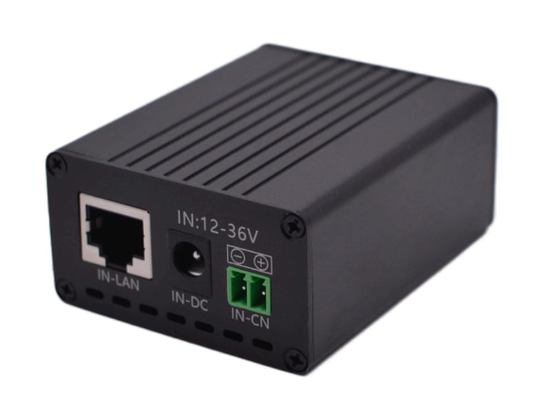
The Maxsol POE24V DC-to-PoE converter documents a 12–36V DC input, adjustable 12–57V PoE output, Gigabit Ethernet and an LCD voltage display. Its documented continuous load when converting 12V to 48V is at most 30W. The stated efficiency of up to 94% is a maximum, not a value that should be assumed for every voltage and load point.
IEEE powered-device detection or negotiation is not established by those facts. Verify the required voltage, polarity, pinout and protocol compatibility before using it with a particular powered device.
For current calculations, use a conservative efficiency assumption based on the current datasheet or measured results. At minimum input voltage, the approximate converter input current is:
Input current = Output power ÷ (Input voltage × Assumed efficiency)
As input voltage falls, current rises. That higher current then increases cable drop, which can pull the converter input even lower. Design checks must account for this feedback rather than calculating at nominal battery voltage only.
Calculate round-trip cable voltage drop
DC voltage-drop calculations must include the outgoing and return conductors. Using only the one-way cable length understates resistance by roughly half for a simple two-wire circuit.
The basic method is:
Round-trip resistance = Conductor resistivity × Round-trip length ÷ Conductor area
Voltage drop = Current × Round-trip resistance
Cable power loss = Current² × Round-trip resistance
Use the actual conductor material, cross-sectional area, operating temperature and route length where available. Terminals, fuse holders, connectors and disconnects add further resistance.
Hypothetical comparison
The following is an illustrative calculation, not measured Maxsol product performance.
Assume:
- 48W delivered over a DC branch;
- 20m one-way cable distance;
- 40m total outgoing-and-return conductor length;
- 2.5mm² copper conductors;
- hypothetical copper resistivity of 0.0175Ω·mm²/m;
- fixed 12V, 24V or 48V source;
- no converter loss, connector resistance or temperature adjustment.
The estimated loop resistance is:
0.0175 × 40 ÷ 2.5 = 0.28Ω
| Nominal bus | Ideal current for 48W | Cable voltage drop | Cable loss | Drop as percentage of nominal voltage |
|---|---|---|---|---|
| 12V | 4A | 1.12V | 4.48W | 9.3% |
| 24V | 2A | 0.56V | 1.12W | 2.3% |
| 48V | 1A | 0.28V | 0.28W | 0.6% |
This comparison explains why 48V distribution is attractive for remote outdoor equipment. Doubling voltage halves current for the same power, and the resistive loss falls with the square of current.
Real systems require a more conservative calculation. Converter losses increase source-side current, while warm conductors have greater resistance. The receiving-end voltage should therefore be checked at:
- lowest expected source voltage;
- highest credible load;
- expected conductor temperature;
- maximum practical cable length;
- worst permitted connector and termination condition.
Do not compensate for excessive cable loss simply by raising an adjustable output voltage unless every connected device and component can safely accept it. The correct remedy may be a larger conductor, a higher distribution voltage, a shorter route or a converter positioned closer to the load.
Size branch protection and service isolation
Outdoor DC branches should not rely only on the battery’s main protection. A large battery can deliver damaging fault current into a small cable even when the connected load normally draws very little.
Each outgoing branch should have protection selected around:
- conductor current-carrying capacity;
- normal and startup current;
- source fault-current capability;
- DC voltage rating of the protective device;
- interruption rating;
- ambient temperature and enclosure conditions;
- coordination with upstream protection.
Place protection close enough to the source to limit the length of unprotected conductor. If several loads share a distribution point, individually protected branches make faults easier to isolate and prevent one cable problem from disabling the entire site.
Do not automatically size a fuse to the load’s normal current. It must carry legitimate startup behaviour without nuisance operation, but it must still protect the smallest conductor and connector in the branch. Confirm the fuse or breaker manufacturer’s DC ratings; an AC rating cannot simply be treated as equivalent.
Provide practical service isolation
Installers should be able to isolate energy sources without removing live conductors. Depending on the architecture, service isolation may be needed between:
- PV array and controller;
- battery and controller;
- battery and load distribution;
- each major outgoing branch;
- converter and downstream equipment.
Switches and disconnects must be suitable for the applicable DC voltage and current. Label source and load sides clearly, particularly where the enclosure can remain energised from either the PV array or battery.
Manage enclosure temperature, moisture and bonding
Electrical calculations made at room temperature are not enough for a sealed outdoor cabinet. Solar loading, equipment heat and limited airflow can raise the internal temperature significantly, while night-time cooling can encourage condensation.
A practical enclosure review should cover:
- expected external and internal temperature range;
- direct sun exposure and shading;
- equipment spacing and heat paths;
- controller and converter derating;
- ventilation or pressure equalisation where appropriate;
- cable-gland sealing;
- drip loops and downward-facing entries;
- drainage strategy;
- separation of power, data and sensitive monitoring wiring;
- corrosion compatibility between metals and fittings.
Do not assume a weather-resistant enclosure eliminates condensation. Moist air can enter during pressure changes, and trapped moisture can affect terminals, protection devices and network connections.
Plan bonding and earthing as a system
Bond exposed conductive parts and provide surge protection according to the site design, equipment instructions and applicable South African requirements. Avoid assuming that DC negative must be bonded to earth: some controllers, converters and monitoring systems require a floating DC supply or a defined bonding arrangement.
Check:
- whether the DC negative is isolated or bonded internally;
- enclosure and mounting-structure bonding;
- PV frame and pole bonding;
- surge-protection conductor routing;
- shield termination for outdoor data cable;
- separation between lightning-current paths and electronics;
- the effect of multiple earth connections on data links.
Where local compliance or lightning exposure is in question, the bonding and protection design should be reviewed by a suitably competent person. There is no universal bonding arrangement that suits every pole, cabinet and solar power architecture.
Test worst-case voltage and recovery
Commissioning evidence should show what the equipment receives under stress, not only the open-circuit battery voltage on a sunny day.
Record at least:
- source voltage at the battery or controller;
- voltage at the start and end of each loaded branch;
- branch current;
- converter input and output voltage;
- total and per-port PoE load where available;
- minimum voltage during startup;
- recovery behaviour after a controlled interruption;
- link status and device restart behaviour;
- enclosure temperature during the test.
A multimeter is suitable for stable readings, but its display may miss a short startup dip. A meter with minimum capture or an appropriately used oscilloscope can reveal transient sag. Testing should be performed safely and within equipment limits.
Useful controlled checks include:
- Start all intended loads from the lowest practical battery state allowed by the system.
- Trigger legitimate high-load modes, such as camera infrared operation.
- Confirm that the converter remains above its input threshold.
- Measure voltage at both ends of the longest DC branch.
- Interrupt and restore power to confirm orderly recovery.
- Check whether one branch fault or disconnection affects unrelated loads.
- Save the readings, load list, cable lengths and protection ratings in the handover record.
Measurements also help identify weak terminations. If the calculated cable drop is modest but the measured drop is much larger, inspect connectors, fuse holders, crimps and disconnects rather than immediately increasing source voltage.
Validate switch input compatibility
The Maxsol IOT2802SFG-S managed solar industrial PoE switch documents eight Gigabit PoE ports, two SFP ports, a 120W PoE budget, 90W BT support, PV and battery monitoring, and PV and battery input at DC22–29.2V. Ports 3–4 can be configured for 24V or 48V PoE.
Its input range illustrates why nominal labels require careful checking. A 12.8V battery kit is not a direct compatible input to a device requiring DC22–29.2V. Verify actual port allocation, charging limits, battery compatibility and supplied configuration against the current datasheet.
The linked solar system, converter and switch are selection examples, not a tested compatible bundle. Their individual voltage ranges and limits must be reconciled as part of the system design.
Which voltage should you choose?
Choose 12V when the battery and loads are natively 12V, cable runs are short, total power is modest and measured voltage drop remains acceptable at minimum source voltage.
Choose 24V when equipment is designed around a 24V battery bus, distances and loads are moderate, or a compatible converter will generate the required PoE output close to the powered equipment.
Choose 48V when distributing meaningful power over longer distances, supporting several loads, or minimising conductor loss is a priority. Confirm that the source, protection, disconnects, converters and loads all tolerate the complete operating range.
In every case, avoid these common mistakes:
- designing only around nominal battery voltage;
- calculating cable resistance using one-way length;
- ignoring startup and converter input current;
- treating any 48V output as standards-compliant PoE;
- combining products because their marketing voltage labels appear similar;
- sizing protection only from average load;
- assuming nominal battery Wh equals delivered energy;
- commissioning without loaded voltage measurements.
The practical next step is to compare the linked Maxsol selection examples against the required port count, device load, cable distance, source voltage, environment, protection arrangement and management features. Confirm current datasheets and supplied configurations before treating any components as a compatible system.