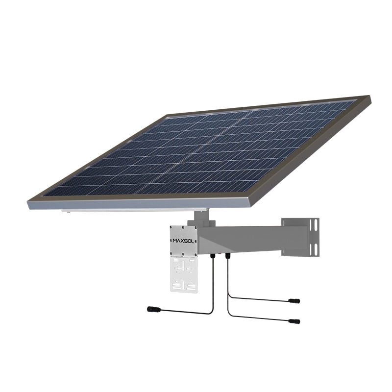
LiFePO4 Battery for Solar CCTV: Practical Sizing Guide
Choose a LiFePO4 battery for solar CCTV with confidence. Calculate usable energy, autonomy, charging needs, temperature limits and monitoring.
By Maxsol Team

A LiFePO4 battery for solar CCTV should be sized around the site’s real 24-hour energy demand, the required number of sunless days and the solar energy available at the installation point. Battery capacity alone is not enough: night-time infrared operation, PoE equipment, wireless links, conversion losses and seasonal weather can all change the result.
For South African security sites, the practical aim is straightforward: keep the camera, network connection and any essential edge equipment running through the night and during reduced solar charging conditions, without repeatedly driving the battery to its operating limits. Start with the continuous load in watts, convert it to daily watt-hours, then assess usable stored energy and recharge capability as one system.
Why battery chemistry matters
LiFePO4, or lithium iron phosphate, is a lithium battery chemistry often selected for outdoor solar-powered CCTV because it offers a useful balance of energy storage, stable voltage behaviour and practical depth of discharge compared with conventional lead-acid battery options.
For a surveillance installation, the battery is not simply a reserve power source. It carries the load every evening, fills the gap during cloudy periods and helps the solar system cope with changing camera demand. A camera with infrared LEDs may draw more power after dark; a PoE switch, wireless bridge or router may also need to operate continuously.
A suitable LiFePO4 battery system can help designers build a more compact off-grid solution, but chemistry does not remove the need for correct design. The system still needs:
- Enough stored energy for the planned overnight and low-sun operating period.
- A solar array and charge controller capable of restoring energy after discharge.
- Proper voltage compatibility between battery, controller, PoE equipment and cameras.
- Protection against unsuitable temperature conditions, over-current and incorrect wiring.
- A sensible monitoring method so faults are found before a security gap develops.
LiFePO4 is not a shortcut to unlimited autonomy
It is tempting to select a larger battery and assume the installation is covered. In reality, stored energy can be exhausted if the daily load is underestimated or if solar input is insufficient for several days.
This is especially important for remote CCTV poles, perimeter cameras, construction sites, farms and wireless backhaul points. The system may be technically sound on a clear day but become energy-deficient during periods of reduced irradiation, increased night-time load or dirty solar panels.
Battery selection must therefore be tied to an energy budget rather than a camera count alone.
Capacity versus usable energy
Battery capacity is commonly quoted in amp-hours (Ah), while stored energy is more useful for solar CCTV sizing and is expressed in watt-hours (Wh). Watt-hours make it easier to compare battery storage with the load consumed by cameras and network devices.
The basic relationship is:
Battery energy (Wh) = battery voltage (V) × capacity (Ah)
For example, a 12.8V, 60Ah battery is rated at:
12.8V × 60Ah = 768Wh
That figure describes nominal stored energy, not necessarily the energy delivered to the final connected equipment. The usable amount depends on the system’s configured discharge limit, battery protection settings, cable losses and any conversion between DC voltages or from DC to AC.
Calculate the CCTV load in watt-hours
First, list every device that must remain online during an outage or overnight period. Include equipment at the solar-powered location, not only the camera itself.
Typical items to check include:
- Fixed, PTZ or thermal cameras.
- Infrared illuminators and camera IR operation.
- PoE switches or injectors.
- Wireless CPEs, point-to-point radios and access points.
- Routers, cellular gateways and telemetry devices.
- Media converters, edge recorders or local storage where fitted.
- DC converters and other equipment that consumes power even when the camera load is low.
Use each device’s actual power draw where possible. Nameplate maximum power is useful for checking peak capacity, but a measured average over day and night is more informative for autonomy planning.
The basic daily calculation is:
Daily energy demand (Wh) = average load (W) × 24 hours
A site with an average 15W load uses approximately:
15W × 24 hours = 360Wh per day
That is before allowing for system losses and before deciding how much reserve is needed. If the camera uses more power at night because its IR LEDs activate, calculate day and night separately:
Daytime energy = day load × daytime hours
Night-time energy = night load × night-time hours
Add the two figures, then include the connected network equipment.
Avoid using all nominal battery energy as the design figure
A battery’s nominal Wh rating is important, but a dependable CCTV design should retain a reserve rather than plan to consume every rated watt-hour. This helps account for variation in load, battery operating limits, cable and conversion losses, and changing environmental conditions.
Rather than assuming a fixed usable-energy percentage for every product, ask the system designer or supplier to confirm:
- The configured low-voltage disconnect point.
- The battery’s permitted discharge range in that system.
- Whether power conversion is required and its expected efficiency.
- The expected standby consumption of controllers, PoE equipment and radios.
- Whether the stated load includes night-time camera power.
This avoids a common specification error: matching nominal battery Wh directly to a calculated load and leaving no operational margin.
Energy capacity and power capability are different
A battery may have enough energy to run a load for many hours but still require the system to handle short peaks. PTZ movement, infrared activation, radio transmission and PoE device start-up can produce temporary higher demand.
Check both:
- Energy requirement: can the system supply the total watt-hours needed over time?
- Peak power requirement: can the battery, controller, cabling and power distribution support the highest expected simultaneous load?
Undersized cables, unsuitable DC converters and overloaded PoE outputs can cause voltage drop or equipment resets even when the battery is not empty.
Autonomy and recharge planning
Autonomy is the length of time a solar CCTV system can operate without enough solar charging. It should be chosen according to the security risk, local weather exposure, seasonal solar variation and how quickly the site can be attended if it goes offline.
For a basic estimate:
Required stored energy = daily load (Wh) × days of autonomy
A 360Wh daily load requiring two days of reserve needs at least 720Wh of energy before allowances for usable energy and system losses. The final battery choice must therefore be assessed against the actual accessible energy, not only its nominal rating.
Plan for the worst realistic operating period
Solar CCTV systems experience their highest battery demand when daylight is shorter, cloud cover reduces charging or the installation is shaded. In South Africa, site conditions can vary sharply between an open, unshaded security pole and a unit affected by trees, buildings, dust or seasonal weather.
Review these points at the survey stage:
- Panel orientation and shading: Even intermittent shade can reduce the useful solar harvest.
- Night-time load: Infrared cameras often use more energy after dark.
- Panel cleanliness: Dust, bird droppings and debris can reduce charging performance.
- Equipment additions: A second camera or radio can materially alter the daily energy budget.
- Service access: Remote installations may need more reserve because fault response takes longer.
- Criticality: A perimeter camera protecting an isolated area may justify more autonomy than a low-risk observation camera.
Do not use a single “hours of runtime” estimate for all solar CCTV systems. Runtime changes with the load profile, available charge, temperature and system configuration.
Recharge matters as much as autonomy
A battery that survives a cloudy day still needs enough solar energy to recharge while the CCTV equipment continues running. If the solar input only matches the live load, the battery cannot recover from a previous night or reduced-sun period.
A recharge plan should account for:
- The site’s ongoing daytime consumption.
- Energy used from the battery overnight.
- Extra solar energy needed to restore reserve capacity.
- Expected solar conditions during the least favourable operating period.
- Charge-controller limits and solar-panel output under real field conditions.
For this reason, selecting a larger battery without checking the charging side can create a slow energy deficit. The system may look acceptable initially but spend too long at a low state of charge after poor weather.
Use measured data when the site is important
For high-value or difficult-to-reach surveillance locations, measure the connected load over a full day and night. A clamp meter, DC power meter or appropriate controller telemetry can reveal differences between assumed and actual consumption.
This is particularly worthwhile where the system has:
- PTZ cameras.
- Long-range infrared illumination.
- Several PoE devices.
- Wireless links with changing traffic.
- Cellular equipment.
- Edge computing or local recording equipment.
Measured figures allow the designer to separate constant consumption from occasional peaks and make a more defensible battery and solar calculation.
Temperature protection and monitoring
Battery performance and charging behaviour are affected by temperature. An outdoor solar CCTV enclosure can become hot in direct sun, while exposed sites can become cold overnight. The battery, charge controller and network equipment should all be considered as part of the environmental design.
LiFePO4 batteries should not be assumed to charge safely in all temperatures. Low-temperature charging in particular needs attention. Confirm the battery’s specified charge and discharge temperature range, and establish whether the system includes an appropriate low-temperature charging protection function.
Protection checks for an outdoor installation
Before specifying or commissioning the system, verify the following:
- Battery charge and discharge temperature limits.
- Whether protection is built into the battery and how it responds to abnormal conditions.
- Charge-controller compatibility with the battery’s voltage and charging profile.
- Over-current protection, fusing and isolation arrangements.
- Cable size, cable length and voltage-drop calculation.
- Enclosure ventilation, weather sealing and condensation management.
- Earthing and surge-protection requirements for the site.
- Whether cameras and network equipment remain within their own operating temperature limits.
The battery is only one part of the resilience picture. A well-sized battery cannot compensate for water ingress, a loose DC connection, a damaged solar cable or an incorrectly configured PoE switch.
Monitor energy, not just online status
A camera showing as online does not prove the power system is healthy. It may be operating from a declining battery and fail later that night.
Where the system supports monitoring, track information such as:
- Battery voltage and state of charge.
- Solar charging activity.
- Load current or power consumption.
- Low-voltage events and protection cut-offs.
- Controller alarms.
- Camera and network-device uptime.
Set practical maintenance checks, particularly after seasonal weather changes or equipment upgrades. Compare recent charging and consumption patterns with the original design assumptions. A gradual change may point to panel soiling, shade growth, a failing connection or higher-than-expected equipment load.
Compare approved LiFePO4 capacities
The following Maxsol solar-system options document LiFePO4 battery storage at 12.8V. They provide useful starting points for comparing nominal energy capacity, but the correct option still depends on the actual CCTV and networking load, required autonomy and solar design.
| Solar system option | Documented LiFePO4 battery capacity | Nominal stored energy | What to evaluate |
|---|---|---|---|
| 60W 30Ah 384Wh solar system | 12.8V 30Ah | 384Wh | Small, low-power load profiles with verified energy demand and recharge margin |
| 80W 45Ah 576Wh solar system | 12.8V 45Ah | 576Wh | Sites needing more stored energy than a 384Wh configuration, subject to actual load calculations |
| 120W 60Ah 768Wh solar system | 12.8V 60Ah | 768Wh | Medium energy budgets where the required reserve and recharge plan support this capacity |
| 200W 100Ah 1280Wh solar system | 12.8V 100Ah | 1280Wh | Higher-demand or longer-autonomy designs, with solar charging checked carefully |
The CS6030 documentation identifies a 12.8V 30Ah 384Wh LiFePO4 battery and MPPT control. For the other listed systems, confirm the exact charge-control, protection, output and monitoring configuration required for the proposed design rather than assuming features are shared across every capacity.
A larger nominal battery can provide a greater storage buffer, but it does not automatically mean the system will recharge adequately. Compare the battery size with both the daily load and the solar resource available at the installation point.
Questions to verify with the system designer
Use this checklist before approving a LiFePO4 battery for solar CCTV:
-
What is the measured average load over 24 hours?
Separate day and night figures, especially for cameras using IR illumination. -
What is the highest possible simultaneous load?
Include camera start-up, PTZ movement, PoE demand, wireless equipment and converters. -
What energy reserve is required?
Define the number of hours or days the system must operate with inadequate solar charging. -
How much nominal battery energy is realistically usable?
Confirm the configured discharge limit, conversion losses and retained reserve. -
Can the solar system recharge the battery after poor weather?
The calculation should include live daytime load as well as recovery charging. -
Is the solar panel location free from predictable shade?
Inspect the site through the likely seasonal conditions, not only at the time of installation. -
Are the battery, controller and loads electrically compatible?
Verify nominal voltage, charge settings, DC output requirements and PoE power requirements. -
What low-temperature and high-temperature protections are needed?
Confirm both charging and discharging limits, plus enclosure heat management. -
What happens when battery voltage becomes low?
Understand the disconnect sequence, restart behaviour and whether equipment recovers cleanly. -
How will the system be monitored and maintained?
Establish who checks charging, battery condition, panel cleanliness, alarms and physical connections.
Common sizing mistakes to avoid
The most frequent problems are usually planning errors rather than battery-chemistry problems:
- Sizing only for camera wattage and forgetting PoE, radios and conversion losses.
- Using daytime power figures for a camera whose night-time IR load is higher.
- Treating nominal battery Wh as fully available usable energy.
- Specifying autonomy without confirming whether the solar array can restore the battery.
- Adding cameras or wireless equipment after commissioning without revisiting the energy budget.
- Ignoring shade, panel dirt, heat, cable voltage drop and environmental protection.
- Assuming a battery system will power an NVR or other AC equipment without confirming its input and conversion requirements.
A properly selected LiFePO4 battery for solar CCTV supports a dependable power design, but it should be specified from measured load, planned reserve, environmental conditions and charging capability—not from a generic runtime claim.
Compare the linked Maxsol models against your required port count, load, distance, power, environment and management requirements before finalising a solar CCTV design.