Off-Grid Solar Design Mistakes: A Fault Guide
Diagnose off-grid solar faults by symptom. Find causes of dawn shutdowns, PoE reboots, poor recharge, winter outages and enclosure heat.
By Maxsol Team

The most common off grid solar power system design mistakes are not simply “too little panel” or “too small a battery”. Failures often come from mixing up watts and watt-hours, overlooking night-time equipment behaviour, using average sunshine instead of the worst design month, or connecting components with incompatible voltage and PoE interfaces.
Fault isolation should start with the observed symptom. Measure the load, battery voltage, charging current and controller status before replacing components. The table below provides a practical starting point for hypothetical CCTV, wireless and remote networking sites; it is not a diagnosis of any actual installation.
| Symptom | Likely design cause | What to measure or verify | Corrective direction |
|---|---|---|---|
| Site shuts down shortly before dawn | Battery energy was calculated from nominal Wh without allowing for conversion losses, protection limits or overnight load peaks | Overnight watt-hours, battery voltage trend, low-voltage disconnect event and actual shutdown time | Recalculate usable delivered energy and reduce unnecessary night loads or increase appropriately matched storage |
| PoE camera, radio or switch repeatedly reboots | Startup current, infrared illumination, radio transmit peaks or DC-to-PoE conversion demand was omitted | DC input voltage at the converter, output voltage during reboot, peak current, PoE pinout and device power mode | Correct voltage drop, converter capacity or interface compatibility; do not assume every “PoE” port behaves identically |
| Battery does not fully recharge | Array capacity is insufficient for the daily load and recovery demand, or MPPT input limits are mismatched | PV open-circuit and operating voltage, charging current, controller status, daily load and available charging window | Match the array to the controller and design for both daily replacement energy and recovery after poor weather |
| System works in summer but fails in winter | Design used annual-average or best-month solar conditions | Site shading, seasonal solar window, daily harvested energy and overnight battery discharge in the design month | Redesign around the selected worst operating month and required service continuity |
| Equipment fails or derates in a hot enclosure | Thermal load, ventilation, solar gain or battery charging-temperature limits were ignored | Internal temperature, component temperature limits, controller derating status and airflow | Reduce solar gain, improve thermal design and verify each component’s permitted operating and charging range |
| Maintenance team cannot isolate the fault | Fuses, connectors, controller display or test points are inaccessible | Ability to reach disconnects, read status indicators and measure each circuit safely | Rework the layout so routine inspection and component isolation do not require dismantling the entire installation |
Mistaking nominal power and energy for usable supply
Watts and watt-hours answer different questions. Watts describe the rate at which equipment consumes or supplies power. Watt-hours describe energy accumulated over time. A 20W load running for ten hours requires 200Wh before losses are considered; it does not require a “20Wh battery”.
This distinction becomes especially important when comparing a solar panel, battery and PoE load:
- Panel watts are a nominal generation rating, not guaranteed daily energy.
- Load watts may change with operating mode.
- Battery watt-hours are nominal stored energy, not automatically usable energy at the load.
- Converter efficiency affects how much battery energy is required.
- Protection settings may disconnect the load before all nominal battery energy is used.
As a hypothetical design assumption, consider a site with a 15W daytime load that rises to 25W for 12 hours at night when infrared lighting is active. Its nominal daily energy is:
- Day: 15W × 12 hours = 180Wh
- Night: 25W × 12 hours = 300Wh
- Total: 480Wh per day before cable, controller and conversion losses
Sizing the battery from 15W alone would miss most of the night demand. Sizing from the 25W peak without considering duration would also be incomplete.
Amp-hours can be equally misleading. A 45Ah battery at 12.8V does not store the same energy as a 45Ah battery at another voltage. For a basic nominal comparison:
Nominal Wh = nominal voltage × Ah
Even then, nominal Wh should not be presented as usable delivered Wh. Temperature, battery protection, discharge current, cable loss and downstream conversion all affect the energy that reaches the equipment.
For the underlying calculation process, use this guide to sizing an off-grid solar power system for CCTV. When evaluating battery chemistry, protection and operating constraints, also review the practical benefits and limitations of LiFePO4 batteries for solar CCTV.
Sizing for average sunshine instead of the design month
An annual average is useful for estimating long-term production, but it can hide the period when the system is most likely to fail. An off-grid site must be assessed against its intended design month, site-specific shading and required continuity.
This matters across South Africa because seasonal conditions, terrain, mounting orientation and local obstructions vary from one site to another. A national or provincial average cannot show whether a particular panel is shaded by a mast, tree, building edge or security structure during the available charging window.
Diagnose a winter-only outage
If a system operates normally for much of the year but shuts down in winter, check the sequence rather than immediately adding battery capacity:
- Record battery voltage or state information at dawn and before sunset.
- Measure daily load energy, including night modes.
- Confirm when the panel first receives direct light and when shading begins.
- Check whether the battery reaches a completed charging state on clear days.
- Review whether the MPPT controller is limiting PV input.
- Establish how many consecutive poor-harvest days the design is expected to tolerate.
A larger battery does not fix inadequate recharge capacity. It may simply take longer to become visibly depleted. If the array can only replace the normal daily load under favourable conditions, it has no meaningful margin to recover energy after overcast weather or an unusually heavy night load.
The correction may involve reducing demand, improving panel exposure, adding correctly matched PV capacity, changing the autonomy requirement or combining these measures. Any array change must remain within the controller’s permitted PV voltage, current and power limits.
Omitting night loads, conversion loss and startup demand
CCTV and wireless loads are rarely constant. Cameras may activate infrared LEDs after dark, radios can draw more power while transmitting, heaters or fans may switch on, and network equipment may experience startup surges after a low-voltage event.
A design based only on a daytime clamp-meter reading can therefore produce a system that appears healthy during commissioning but fails shortly before dawn.
Build a load schedule, not just a device list
For each connected device, document:
| Load characteristic | Questions to answer |
|---|---|
| Normal operating power | What does the device consume during stable operation? |
| Night operating power | Does infrared illumination or another night function increase demand? |
| Startup demand | What happens when all devices restart together? |
| Duty cycle | Is the load continuous, scheduled or event-driven? |
| Input interface | What voltage range, polarity and connector does it require? |
| PoE method | Does it require passive voltage, a particular pinout or protocol negotiation? |
| Cable effect | What voltage reaches the device at the end of the actual cable run? |
Repeated PoE reboots often create a cycle: a device starts, input voltage drops, the converter or battery protection disconnects, voltage recovers, and the device tries to start again. The battery may still show an apparently reasonable open-circuit voltage, so measurements must be taken while the fault is occurring.
Conversion efficiency must also be budgeted conservatively. A converter’s stated maximum efficiency is not a guaranteed value at every voltage and load. Use the relevant operating point from current documentation where available and retain engineering margin rather than calculating from a best-case headline figure.
Mismatching battery, MPPT and PoE interfaces
Components can each be correctly rated in isolation and still be incompatible as a system. Confirm the full power path:
Panel → MPPT controller → battery → protected DC output → converter or injector → powered device
At every interface, verify voltage range, current capacity, polarity, connector type, protection behaviour and communication or PoE requirements.
Battery and controller mismatch
Check the controller’s current datasheet and supplied configuration for:
- Permitted PV open-circuit voltage
- PV operating-voltage range
- Maximum charging current
- Maximum supported PV power
- Battery voltage and chemistry settings
- Low-voltage disconnect and reconnect thresholds
- Battery charging-temperature restrictions
- Temperature sensing and protection behaviour
Do not assume that “MPPT” means any panel arrangement can be connected. Panels wired in series may exceed the controller’s PV voltage limit, especially under conditions that raise open-circuit voltage. Parallel arrangements may exceed current or power limits. Resolve conflicting source specifications through the current manufacturer documentation, not by guessing.
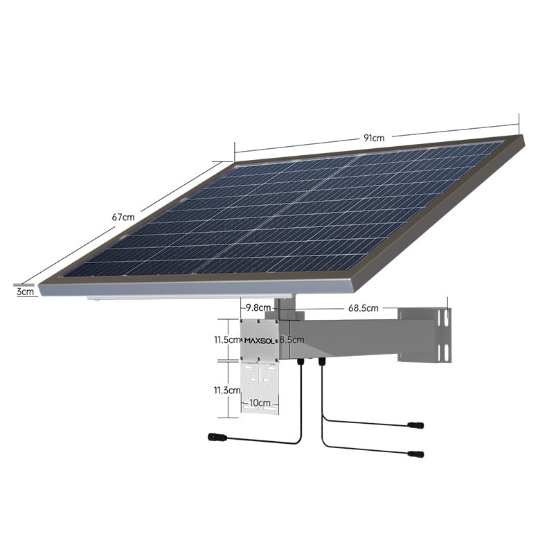
Two examples for initial comparison are the Maxsol CS8040 80W and 576Wh solar system, which documents an 80W monocrystalline panel, 12.8V 45Ah 576Wh LiFePO4 battery, MPPT controller and three DC12V outputs, and the Maxsol CS12060 120W and 768Wh solar system, which documents a 120W panel, 12.8V 60Ah 768Wh LiFePO4 battery, MPPT controller and three DC12V outputs. Optional RS485 is documented for both.
These nominal specifications are selection inputs, not proof of usable runtime or suitability for a specific site. Confirm the current controller limits, battery configuration, environmental constraints and supplied options before specifying either system.
PoE is not one universal DC interface
A device labelled “PoE” may expect standards-based detection and negotiation, passive power at a fixed voltage, or a specific polarity and pin assignment. Supplying the correct number of volts is not enough if the protocol, pinout or polarity differs.
The Maxsol POE24V adjustable DC-to-PoE converter accepts 12–36V DC and provides adjustable 12–57V PoE output, Gigabit Ethernet and an LCD voltage display. Its documented continuous load for 12V-to-48V conversion is no more than 30W, while the stated efficiency of up to 94% is a maximum rather than a guaranteed design value.
IEEE powered-device detection or negotiation is not established by those facts. Before pairing the converter with a camera, access point, CPE bridge or switch, verify:
- Required input voltage and tolerance
- Passive or negotiated PoE method
- Polarity and powered pairs
- Continuous and startup power
- Cable length and conductor resistance
- DC input voltage under load
- Converter output setting
- Behaviour after battery low-voltage recovery
The converter and linked solar systems are examples for selection, not a tested compatible bundle.
Ignoring shading, temperature and maintenance access
A sound electrical calculation can still fail because of the physical installation. Shading, heat and inaccessible components directly affect harvest, equipment operation and the time required to isolate a fault.
Shading must be checked across the charging window
A small shadow across part of a panel can matter, but its effect depends on panel construction, bypass arrangements and the changing position of the shadow. Do not assess the site from a single midday photograph.
Inspect the proposed location at relevant times or use an appropriate solar-path assessment method. Consider:
- Mast and antenna shadows
- Fences, parapets and roof edges
- Vegetation growth
- New structures or equipment
- Soiling and safe cleaning access
- Panel orientation and mounting stability
Measure actual PV voltage and charging current when the suspected shadow crosses the panel. This distinguishes a shading problem from a controller limit, damaged connection or depleted battery absorbing all available charge.
Hot enclosures need a thermal design
Outdoor cabinets can experience internal temperatures that differ substantially from the surrounding air. Controllers, converters, batteries and network devices may each have separate operating, charging and derating limits.
Verify the current documentation for every installed component. In particular, check battery charging-temperature limits and protection because a battery may permit discharge under conditions where charging is restricted.
Thermal planning should address enclosure colour and solar exposure, internal spacing, heat generated by converters and network equipment, airflow strategy, ingress-protection requirements and whether ventilation introduces dust, moisture or insects. Adding an uncalculated fan can create another continuous load and another possible failure point.
Design for fault isolation
Installers should be able to reach fuses, disconnects, status displays and test points without removing unrelated equipment. Labels should identify the panel input, battery circuit, each DC output and the powered device served.
Leave enough space to:
- Measure voltage on both sides of protection devices
- Disconnect one load without shutting down the entire site
- Read controller fault codes
- Inspect connectors for heat or corrosion
- Replace a fuse with the specified type
- Check cable strain relief and gland condition
- Access communication ports where fitted
Remote monitoring can help identify trends, but it does not replace accessible isolation points and local measurements.
Validate the corrected design with a commissioning checklist
Commissioning should prove that the assembled system behaves as expected under realistic load conditions. A midday battery-voltage reading alone is not sufficient.
Electrical and configuration checks
- Record panel, controller, battery, converter and load model details.
- Confirm panel wiring and measure polarity before connection.
- Verify PV open-circuit voltage against the controller limit.
- Confirm battery chemistry, voltage and controller settings.
- Record low-voltage disconnect and reconnect settings.
- Verify fuse or breaker ratings and cable conductor sizes.
- Measure voltage drop on the longest or highest-load circuit.
- Confirm PoE voltage, polarity, pinout and protocol compatibility.
- Test the maximum expected continuous load.
- Observe the system while all powered devices start together.
Energy and recharge checks
- Measure daytime and night-time load separately.
- Activate infrared illumination and other conditional loads.
- Record overnight watt-hours rather than relying only on instantaneous watts.
- Check battery condition near dawn.
- Confirm charging begins as expected after sunrise.
- Record PV and battery values during the main charging period.
- Confirm the array can support the planned recovery requirement, not merely the immediate daytime load.
- Reassess the calculation for the selected design month and site shading.
Environmental and maintenance checks
- Record enclosure temperature under representative operation.
- Verify component operating and charging-temperature limits.
- Confirm panel and cabinet mounting security.
- Inspect cable glands, drip loops, earthing arrangements and strain relief.
- Ensure protection devices, displays and test points remain accessible.
- Label circuits and leave the final settings and wiring record for maintenance personnel.
- Define what data should be collected after a shutdown or reboot event.
If the corrected design still fails, preserve measurements from immediately before and during the event. Battery voltage under load, controller status, PV input, converter input and output, and the exact reboot sequence provide far more diagnostic value than a reading taken after the system has recovered.
As a practical next step, compare the linked Maxsol selection examples against the site’s actual port count, load profile, cable distance, input and output power, environmental conditions and management requirements. Verify the current datasheets and supplied configuration before treating any solar system, converter and network device as a compatible combination.