How to Size Solar Power for an Outdoor PoE Device
Learn to calculate daily PoE energy, battery autonomy and design-month solar input, with losses and compatibility checks made explicit for outdoor sites.
By Maxsol Team

To calculate solar power requirements for an outdoor PoE device, first establish the complete load in watts and its operating hours. Convert each load to daily watt-hours, add converter, cable and auxiliary losses, multiply by the required days of autonomy, and then divide by the permitted usable battery fraction. Finally, size the solar array using the site’s design-month peak-sun-hours and an explicitly selected system derating factor.
Keep energy sizing separate from PoE compatibility. A battery and panel may provide enough energy while the converter still has the wrong voltage, polarity, pinout or PoE protocol for the powered device.
Define the complete PoE load and duty cycle
Start at the powered equipment, but include every component that draws energy from the solar system. Depending on the installation, this may include:
- IP cameras, including infrared illumination, heaters or illuminators
- Wireless access points, CPE radios or point-to-point bridge units
- PoE switches or injectors
- DC-to-PoE converters
- Routers, optical network terminals or cellular gateways
- Cabinet fans, controllers, relays and monitoring equipment
- Night lighting or other auxiliary DC loads
A nameplate maximum is useful for checking worst-case capacity, but it may not represent typical daily consumption. Where possible, measure the equipment under realistic conditions, including night mode, radio traffic, recording activity and start-up.
Separate continuous and intermittent loads
Calculate each operating state independently:
Daily endpoint energy:
Energy (Wh/day) = Power (W) × Operating time (hours/day)
For example, consider a purely illustrative outdoor system with these measured or specified endpoint loads:
| Load state | Power | Operating period | Daily energy |
|---|---|---|---|
| Camera base load | 8W | 24 hours | 192Wh |
| Camera infrared increment | 5W | 12 hours | 60Wh |
| Wireless bridge | 7W | 24 hours | 168Wh |
| Endpoint total | 420Wh/day |
These figures are calculation examples, not expected values for a particular camera or radio. Actual consumption must be measured or obtained from the relevant equipment documentation.
If several cameras are connected, repeat the calculation for each device rather than multiplying one figure unless the models, settings and duty cycles are genuinely identical. The guide to calculating a PoE power budget for security cameras explains how to check simultaneous switch or injector capacity separately from daily solar energy.
Use maximum demand and average energy for different checks
Two calculations are required:
- Maximum simultaneous watts determine whether converters, conductors, protection devices and PoE equipment can support the load at any instant.
- Daily watt-hours determine battery capacity and solar replenishment requirements.
A 20W load operating for two hours consumes less daily energy than a continuous 8W load, but the 20W load still requires the power path to support at least its instantaneous demand.
Add converter, cable and auxiliary losses
Power drawn from the battery will be higher than power consumed at the PoE endpoint. Account for conversion losses, cable losses and supporting equipment explicitly.
A practical calculation is:
Battery-side energy = Endpoint energy ÷ Conversion efficiency + Cable-loss energy + Auxiliary energy
Do not automatically use a converter’s advertised maximum efficiency as a design value. Efficiency changes with input voltage, output voltage and load. Use a measured value, an applicable performance curve, or a conservative engineering assumption that is clearly recorded in the design.
Avoid double-counting losses
Choose one measurement boundary and apply it consistently:
- If measuring power at the PoE device, add upstream cable and conversion losses.
- If measuring the DC input to the final converter with the actual device and cable connected, those converter and downstream cable losses are already represented.
- If measuring at the battery output, most downstream losses are already included, but separate loads connected elsewhere still need to be added.
Battery-side measurement with the intended cable length and equipment operating in its demanding modes is generally the clearest commissioning reference.
Calculate PoE cable loss
Cable loss depends on conductor resistance and current:
Cable loss (W) = Current² × Loop resistance
Long outdoor Ethernet runs can create meaningful voltage drop, particularly where a lower voltage causes higher current for the same power. Cable category alone does not establish actual resistance; conductor material, conductor size, temperature, terminations and run length also matter.
Measure voltage at the powered device under load. A no-load voltage reading will not reveal the full voltage drop.
Include all auxiliary consumption
Small continuous loads can have a large daily effect. A 2W monitoring device, for example, uses:
2W × 24 hours = 48Wh/day
That may be more significant than a larger device that operates only briefly. Include controller self-consumption, network equipment, cabinet ventilation and any standby loads specified for the site.
Using the illustrative 420Wh/day endpoint load above, a designer might calculate:
420Wh ÷ selected conversion efficiency
Then add separately measured or assumed daily cable and auxiliary energy. Every assumption should appear in the design sheet so it can be replaced with commissioning measurements later.
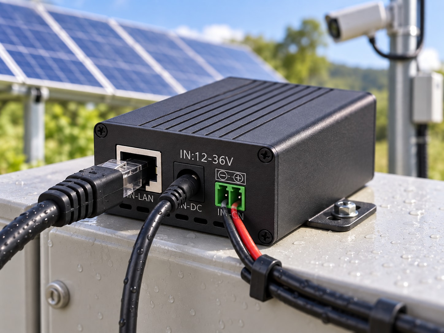
The Maxsol POE24V DC-to-PoE converter accepts 12–36V DC and provides adjustable 12–57V PoE output, Gigabit Ethernet and an LCD voltage display. Its documented continuous load when converting 12V to 48V is no more than 30W. The stated conversion efficiency of up to 94% is a maximum, not a guaranteed design efficiency, so it should not be inserted into every solar calculation without verifying the actual operating point.
Convert power into daily energy demand
Once all loads and losses are identified, build a 24-hour energy schedule.
For each load or operating mode:
Daily energy = Watts × Hours per day
Then calculate:
Total daily demand = Sum of all daily load energy and losses
A simple worksheet can use the following structure:
| Item | Operating power | Hours per day | Adjustment | Daily energy |
|---|---|---|---|---|
| PoE device base mode | Measured W | Hours | None or stated factor | Wh |
| Night or high-load mode | Additional W | Hours | None or stated factor | Wh |
| Second PoE device | Measured W | Hours | None or stated factor | Wh |
| Conversion loss | — | — | Measured or calculated | Wh |
| Cable loss | Loss W | Active hours | Measured or calculated | Wh |
| Auxiliary equipment | Measured W | Hours | None | Wh |
| Total | Wh/day |
For loads that vary unpredictably, use logged average energy from a representative operating period and separately record the observed maximum demand. Security cameras should be checked at night with infrared enabled, while wireless equipment should be observed during realistic traffic rather than only while idle.
Do not size from watts alone
A panel rated at 120W does not produce 120Wh per day; watts describe instantaneous power. Similarly, a 30W PoE device does not automatically need a 30W panel. Its energy requirement depends on operating time, losses, available solar input and the need to recharge the battery after low-sun periods.
Daily watt-hours are therefore the link between the PoE load, storage and solar array.
Select autonomy and usable storage assumptions
Autonomy is the number of days the system should operate without sufficient solar replenishment. It is a design decision based on site criticality, expected weather, access for maintenance and the consequences of an outage.
Required usable storage is:
Usable battery energy = Daily demand × Days of autonomy
Nominal battery capacity must then account for the permitted usable fraction:
Required nominal battery Wh = Usable battery energy ÷ Permitted usable fraction
The permitted usable fraction should come from the battery system’s applicable documentation and the designer’s life-cycle strategy. Do not assume that all nominal watt-hours can be delivered to the load. Battery management limits, discharge policy, temperature, ageing, wiring and conversion losses may all reduce available energy.
For the earlier example, if the final calculated demand were represented as Eday, the calculation would be:
Required nominal storage = Eday × Selected autonomy ÷ Selected usable fraction
Keeping the variables visible is better than inserting a universal percentage. It prevents an unverified assumption from becoming an apparent product specification.
Compare storage using watt-hours
Amp-hours cannot be compared properly without voltage. Convert them as follows:
Nominal watt-hours = Nominal voltage × Amp-hours
Two documented examples illustrate the distinction:
- The Maxsol CS8040 80W and 576Wh solar system includes an 80W monocrystalline panel, a 12.8V 45Ah — 576Wh — LiFePO4 battery, an MPPT controller and three DC12V outputs.
- The Maxsol CS12060 120W and 768Wh solar system includes a 120W monocrystalline panel, a 12.8V 60Ah — 768Wh — LiFePO4 battery, an MPPT controller and three DC12V outputs.
These are nominal storage figures. They must not be treated as guaranteed delivered energy or converted into a universal runtime. Compare each system’s nominal watt-hours with the project’s calculated storage requirement only after applying the project-specific usable fraction and downstream losses.
Check peak current as well as stored energy
A battery may have enough watt-hours but still be unsuitable if the combined load demands more instantaneous current than the power path permits.
At a simplified level:
DC current (A) = Power (W) ÷ Voltage (V)
Actual input current will be higher when conversion losses are included. Verify battery output limits, controller output limits, fuse ratings, conductor size, connector ratings and converter input requirements against maximum simultaneous demand and start-up behaviour.
Estimate design-month solar input
Size the solar array for the month in which the relationship between available sunlight and energy demand is least favourable, not from an annual average.
Obtain site-specific design-month peak-sun-hours from a credible solar resource or project dataset. South African sites can differ materially by region, season, terrain, panel orientation and local shading, so a generic national figure is not a sound substitute for site data.
The basic array calculation is:
Required array watts = Daily energy demand ÷ (Design-month peak-sun-hours × Solar-chain factor)
Where:
- Daily energy demand is the battery-side Wh/day calculated earlier.
- Design-month peak-sun-hours comes from the selected site dataset.
- Solar-chain factor represents the designer’s documented allowance for applicable panel, controller, wiring, temperature, orientation, shading and soiling effects.
There is no universal solar-chain factor. Each element should either be calculated from available data or combined into a clearly labelled project assumption.
Allow for both daily operation and battery recovery
An array that merely matches an average day’s load may take too long to recover after several poor-solar days. If recovery time is important, calculate the additional charging energy:
Daily recovery energy = Energy to be restored ÷ Permitted recovery days
Then use:
Array design energy = Normal daily demand + Daily recovery energy
The array calculation becomes:
Required array watts = Array design energy ÷ (Design-month peak-sun-hours × Solar-chain factor)
Confirm that the battery and charge controller can accept the resulting charging power. Increasing panel wattage does not help if controller limits, battery charging limits or system voltage prevent that energy from being used.
For a broader CCTV-focused process covering load assessment, storage and generation together, see the guide to sizing an off-grid solar power system for CCTV.
Account for the actual installation
Before finalising panel wattage, assess:
- Shading throughout the design month, not only at midday
- Panel direction and tilt
- Dust, bird fouling and the practical cleaning interval
- Module temperature and airflow
- Cable distance between panel, controller and battery
- Space for the required module arrangement
- Mounting exposure and environmental protection
- Whether future equipment will increase the daily load
Where shading is intermittent or difficult to model, measured site data is preferable to an arbitrary percentage allowance.
Verify voltage, protocol and commissioning measurements
Energy capacity does not establish electrical or PoE compatibility. Verify the complete path from battery output to powered device before connecting equipment.
Check the DC and PoE interfaces
Confirm all of the following:
- Battery or controller output voltage range
- Converter input voltage range
- Converter output voltage under load
- Maximum continuous and peak load
- Connector polarity
- PoE pinout and pair usage
- Ethernet data rate requirements
- Whether the powered device requires passive PoE or IEEE 802.3 detection and negotiation
- Surge, earthing and overcurrent protection requirements
- Environmental suitability of enclosures, connectors and cable entries
For the POE24V example, adjustable output voltage does not prove compatibility with a particular camera, access point or radio. IEEE powered-device detection or negotiation is not established by the documented facts. Voltage, polarity, pinout and protocol must be confirmed before connection.
The linked converter and solar systems are calculation examples, not a tested compatible bundle.
Commission the installed system under realistic load
After installation, record at least:
- Battery voltage at rest and under maximum load
- Converter input voltage and current
- PoE output voltage at the converter
- Voltage at the powered device end of the Ethernet run
- Daytime, night-time and peak operating power
- Auxiliary load power
- Solar charging current under recorded conditions
- Overnight energy use
- Battery state before sunrise and after the charging period
- Network stability during high-load conditions
Where possible, log several representative days rather than relying on one spot measurement. Compare the measured daily energy with the design worksheet, then update assumptions that were too optimistic or unnecessarily conservative.
Common sizing mistakes
Avoid these recurring errors:
- Using only the PoE device’s nominal watts
- Ignoring night-time infrared or heater operation
- Treating rated panel watts as daily energy
- Assuming all nominal battery Wh are usable
- Applying a converter’s maximum efficiency as a guaranteed value
- Omitting switches, radios, controllers or monitoring equipment
- Using annual-average sunlight instead of the design month
- Forgetting battery recovery after poor-solar periods
- Double-counting losses already included in a battery-side measurement
- Assuming sufficient energy means compatible PoE
A practical final sizing checklist
Before choosing equipment, ensure the design file states:
- Measured or documented watts for every load state
- Hours per day for each operating state
- Maximum simultaneous power
- Converter and cable-loss method
- Total battery-side Wh/day
- Required autonomy
- Permitted usable battery fraction
- Required nominal storage
- Site-specific design-month solar resource
- Solar-chain assumptions
- Required recovery period
- Calculated array wattage
- DC voltage, polarity, pinout and PoE protocol
- Commissioning measurements to be taken
The most reliable next step is to compare the linked Maxsol solar-system and converter examples with the project’s calculated port count, measured load, cable distance, required power, environmental conditions and management requirements. Select only after both the energy calculation and the interface checks have been completed.