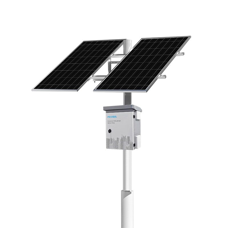
Solar Security Cameras for Farms, Car Parks and Remote Sites
Compare solar camera needs for farms, car parks and remote facilities, including power, connectivity, mounting, autonomy and maintenance.
By Maxsol Team

Solar-powered security cameras can serve farms, car parks and remote facilities where grid power or fixed data connections are impractical. However, these sites should not share one standard design: farms often need long-distance coverage, car parks require clear views of vehicle and pedestrian movement, and remote facilities place greater emphasis on autonomy and maintainability.
When specifying solar powered security cameras for farms, parking lots and remote facilities, assess six factors separately: camera coverage, solar exposure and shade, mounting conditions, network connectivity, required autonomy and service access. The camera, solar power equipment and communications link must then be selected as separate but compatible parts of the system.
Farm boundaries and agricultural buildings
Agricultural surveillance commonly spans a mixture of open land, gates, sheds, livestock areas, equipment stores and buildings. The challenge is rarely limited to powering one camera. The designer must also establish where useful images can be captured and how data will travel across the property.
Coverage is distributed rather than concentrated
A camera at a farm entrance may need a narrow view of vehicles entering through a gate. A camera monitoring a shed or fuel storage area may require a wider field of view. Boundary monitoring can introduce longer distances and multiple isolated mounting points.
This affects the design in several ways:
- Each camera position may need its own solar supply and communications path.
- A single tall mounting point may provide better wireless visibility but poorer detail at ground level.
- Vegetation, trees, silos and buildings can obstruct both sunlight and wireless links.
- Livestock, machinery and seasonal activity may expose equipment to impact, dust or accidental cable damage.
- Camera functions such as infrared lighting, heaters, audio or motorised movement can materially change the electrical load.
Solar exposure should be assessed at the proposed panel position, not merely somewhere nearby. A gatepost may provide the preferred camera angle while receiving poor sunlight due to trees or a roofline. Moving the panel to a clearer position can require longer DC cabling, which introduces voltage drop and protection considerations.
Connectivity may determine the mounting location
Where trenching fibre or copper is not practical, a directional wireless bridge may connect a remote camera point to a recorder or network building. The documented Maxsol CPE295 5.8GHz wireless CPE has a 2x2 14dBi directional MIMO antenna, one Gigabit LAN port, IEEE 802.3af/at or 9–48V DC power support, and documented full-load consumption of 6.5W.
Those specifications do not guarantee a particular distance or video throughput. Product range and wireless-rate labels should not be treated as site performance commitments. Confirm line of sight, mounting alignment, interference, link capacity, cable arrangement and applicable local radio requirements before selection.
On a farm, even partial obstruction can change over time. Trees grow, crops vary by season, and new structures or parked machinery can enter the signal path. The handover should therefore record the link direction, alignment reference and expected clear path.
Parking entrances and open lots
A car park usually has more concentrated activity than a farm boundary, but image requirements can be more demanding. Entrances, payment points, pedestrian routes and rows of vehicles each require different camera positions and fields of view.
Entrances need controlled viewpoints
At an entrance or exit, the key design issue is often image geometry rather than maximum coverage. A camera intended to observe vehicles should have a stable, deliberate angle to the lane. Mounting too high or too far from the target area may provide a broad overview without the required detail.
Solar panel placement can also conflict with camera placement. The camera may need to face a particular lane, while the panel requires good solar exposure and a structure able to support its wind load. They do not necessarily have to face the same direction or share the same bracket.
Consider:
- vehicle queuing and turning positions;
- headlights and changing contrast after dark;
- moving shadows from trees, buildings or shade structures;
- the risk of vehicles striking low poles or cabinets;
- access for cleaning without closing a busy lane;
- whether one camera is expected to provide both overview and identification-level detail.
Solar availability can differ across the same car park. A pole in an open section may receive relatively clear exposure, while an entrance beside a building may be shaded for part of the day. Each position requires its own assessment.
Open lots can support shared infrastructure, with limits
Where several cameras are close together, it may be practical to centralise power, switching or wireless backhaul. This can reduce the number of batteries and communications links, but it also creates a common point of failure.
Long cable runs from a shared solar cabinet must be checked for voltage drop, surge exposure, cable protection and the total simultaneous load. A shared system should not be selected by adding camera wattages alone. Include network equipment, conversion losses, controller consumption and any loads that operate only at night.
Security of the solar equipment also matters. A panel, battery enclosure or exposed cable can itself become a target for tampering. Enclosure ingress resistance and impact resistance address different risks; the practical distinctions are explained in this guide to IP65 and IK10 for outdoor CCTV enclosures. The appropriate rating and construction still need to be confirmed for the actual installation environment.
Remote facilities with limited service access
Remote pump stations, telecommunications points, utility compounds, storage sites and similar facilities often have fewer cameras than a car park, but maintenance may take substantially longer. The cost and difficulty of reaching the site can be more important than the initial equipment count.
Autonomy is a design requirement, not a battery label
A battery’s nominal watt-hour figure does not equal usable delivered energy. Actual autonomy depends on system voltage, allowed depth of discharge, controller behaviour, conversion losses, temperature, battery protection settings, cable losses and the load profile.
For example, consider a hypothetical design assumption, not measured product performance:
- camera and associated load: 12W continuously;
- communications equipment: 6.5W continuously;
- assumed miscellaneous and conversion allowance: 3.5W;
- assumed total load: 22W;
- daily energy demand: 22W × 24 hours = 528Wh per day.
This calculation is only an initial load estimate. It does not establish how many days a particular battery will run the system, nor does it account for charging conditions. Solar yield, battery limits and system losses must be modelled using site measurements and the current component datasheets.
Remote sites may need a larger design margin because a short interruption cannot be addressed quickly. That margin should be based on the agreed service response, acceptable downtime and measured seasonal conditions—not on a universal “days of backup” rule.
Remote monitoring should expose useful faults
A system is easier to support when technicians can distinguish between:
- loss of camera power;
- loss of network communication;
- weak wireless signal;
- low battery state;
- solar charging problems;
- recorder or application failure.
Optional interfaces do not automatically provide a complete remote-management function. For example, RS485 is documented as optional for the CS12060 configuration, but the exact supplied configuration, accessible data and integration method must be confirmed.
Remote diagnostics should also avoid consuming disproportionate energy or data. Specify what information must be visible, how alarms will be delivered and what can realistically be reset remotely.
Compare power, connectivity and mounting needs
The following matrix compares three hypothetical deployment types. It is a planning aid, not a representation of completed customer sites or guaranteed product performance.
| Requirement | Farm boundary or building | Car park entrance or open lot | Remote facility |
|---|---|---|---|
| Coverage priority | Distributed gates, sheds, equipment and boundaries | Defined lanes, pedestrian routes and vehicle areas | Critical assets, access points and operational status |
| Shade risk | Trees, rooflines, silos and seasonal vegetation | Buildings, shade structures, trees and adjacent poles | Terrain, structures, dust accumulation and local obstructions |
| Mounting priority | Clear camera view and wireless line of sight across long distances | Stable lane angle, collision protection and controlled access | Robust mounting with minimal need for adjustment |
| Connectivity | Directional wireless, local recording or a mixed topology | Shared network infrastructure may be practical | Independent backhaul or local recording with remote health reporting |
| Autonomy emphasis | Varies by point; isolated boundary sites may need larger margins | Often balanced against easier physical access | High, because delayed servicing can extend an outage |
| Service access | Variable; some points are accessible by farm road | Usually comparatively accessible, but work may disrupt traffic | Limited, costly or weather-dependent |
| Common design error | Assuming every point has the same sun and link conditions | Using one overview camera for every image objective | Selecting from nominal battery capacity without a load and autonomy calculation |
A useful comparison should also identify failure consequences. Losing an overview camera for a few hours may carry a different operational risk from losing the only camera at a remote access gate. Rank each location by criticality before assigning autonomy and redundancy requirements.
Treat imaging, power and networking as separate functions
The linked Maxsol products supply solar power or network connectivity; they do not provide camera imaging functions. A complete solution still requires a camera selected for the required scene, image detail, recording arrangement and environmental conditions.
Likewise, a power system with several DC outputs is not automatically compatible with every camera or radio. Confirm voltage, current, connector type, polarity, start-up demand and grounding requirements for every connected device.
Select components from measured requirements
Component selection should begin with a load schedule and site survey rather than a product wattage label.
1. Record every electrical load
For each device, obtain or measure:
- normal operating power;
- peak or start-up power;
- daytime and night-time consumption;
- supply voltage;
- whether infrared lighting, heaters or motors change the load;
- converter or PoE losses;
- hours of operation per day.
Where possible, measure representative equipment in its intended operating modes. Nameplate maximums can be useful for protection design, while measured profiles can improve energy modelling. Keep both values in the handover.
2. Define the autonomy target
State how long the system should operate under the selected low-charging assumption and what level of interruption is acceptable. This is a project requirement, not a fixed property of a battery.
The Maxsol CS12060 120W, 60Ah, 768Wh solar system documents a 120W monocrystalline panel, 12.8V 60Ah 768Wh LiFePO4 battery, MPPT controller and three DC12V outputs. It is a selection example for loads that fit the verified electrical and environmental requirements, not evidence of a particular camera runtime.
For larger calculated loads, the CS400150 400W, 150Ah, 1920Wh solar system documents two 200W panel modules, a 12.8V 150Ah 1920Wh LiFePO4 battery, MPPT control and four DC12V outputs. Its larger nominal figures still do not establish usable energy, guaranteed autonomy or 24/7 performance at a specific site.
For both examples, verify the current datasheet and supplied configuration. Checks should include controller PV voltage, current and power limits; battery charging temperatures; protection behaviour; output ratings; cable requirements; and compatibility with all connected equipment.
A structured method for moving from load calculations to panel and battery requirements is covered in the guide to sizing an off-grid solar power system for CCTV.
3. Survey the communications path
A wireless survey should record:
- endpoint coordinates or an equivalent site reference;
- mounting height;
- clear or obstructed line of sight;
- distance;
- expected interference;
- required application throughput;
- cable length from radio to connected equipment;
- power method;
- local recording behaviour if the link fails.
Video bitrate is affected by resolution, frame rate, compression, scene movement and camera configuration. Multiply realistic per-camera demand by the number of simultaneous streams, then allow for management traffic and link variation. Do not select a wireless link solely from a headline rate.
4. Confirm mounting and environmental requirements
Inspect the actual structure before specifying brackets or panel sizes. Confirm:
- pole or wall condition;
- available panel orientation and tilt;
- wind exposure and structural loading requirements;
- shading throughout relevant parts of the day;
- drainage and water paths;
- dust, insects, corrosion and vegetation;
- lightning and surge exposure;
- tamper risk;
- safe maintenance access.
The camera’s preferred viewpoint, the panel’s solar position and the radio’s line of sight may point in different directions. Use an arrangement that allows each component to perform its own function without creating unsafe leverage or inaccessible service points.
5. Produce a requirements handover
A proper handover prevents procurement teams from receiving a vague request for “a solar camera kit”. At minimum, provide:
| Handover field | Required information |
|---|---|
| Surveillance objective | What activity or asset must be observed |
| Camera load | Normal, peak, night-time and accessory consumption |
| Network demand | Number of streams, expected bitrate and recording destination |
| Solar assessment | Panel location, shade observations and site assumptions |
| Autonomy target | Required operating period under the stated low-charge scenario |
| Mounting | Structure, height, orientation, access and impact risks |
| Power interface | Voltage, current, connector, polarity, PoE or DC arrangement |
| Communications | Link path, distance, obstruction, interference and power method |
| Environment | Temperature range to confirm, dust, moisture, corrosion and surge risks |
| Maintenance | Inspection interval, cleaning method, access equipment and spares |
| Acceptance criteria | Tests, readings, image checks and documentation required |
Any assumption that has not been measured should be marked clearly. That allows the installer, network designer and buyer to identify where additional survey work is needed.
Plan maintenance and acceptance checks
Solar surveillance is not maintenance-free. Panels become dirty, vegetation grows, brackets move, connectors degrade and wireless conditions change. Maintenance planning should reflect the difficulty of reaching each site.
For farms, include vegetation control, animal-related damage and changes to wireless paths. In car parks, inspect collision protection, tampering and whether new structures alter shade or camera views. At remote facilities, prioritise remote health information and carry the likely replacement parts on the first visit.
A practical maintenance checklist includes:
- clean and inspect solar modules using an appropriate safe method;
- check brackets, poles, fasteners and cable supports;
- inspect glands, seals, connectors and exposed cable;
- review battery and controller information available from the supplied configuration;
- verify camera image direction, focus and night operation;
- test recording and retrieval;
- check wireless signal and application throughput;
- confirm date, time and event records;
- remove vegetation or new obstructions;
- record all readings and changes against the installation baseline.
Acceptance testing should take place after the complete system is installed, not only on a workbench. Confirm operation during the camera’s higher-load modes, verify the network while video is streaming, and inspect image quality under the relevant lighting conditions.
The acceptance record should also state what was not proven. A short commissioning test cannot demonstrate year-round solar autonomy, long-term battery service life or performance during every weather condition. These limitations should remain visible to the system owner.
The practical next step is to compare the linked Maxsol power and wireless examples against the project’s measured port count, continuous and peak load, link distance, power interfaces, environmental exposure and management requirements. Treat them as individual selection options rather than a tested compatible bundle, and confirm current datasheets and supplied configurations before procurement.