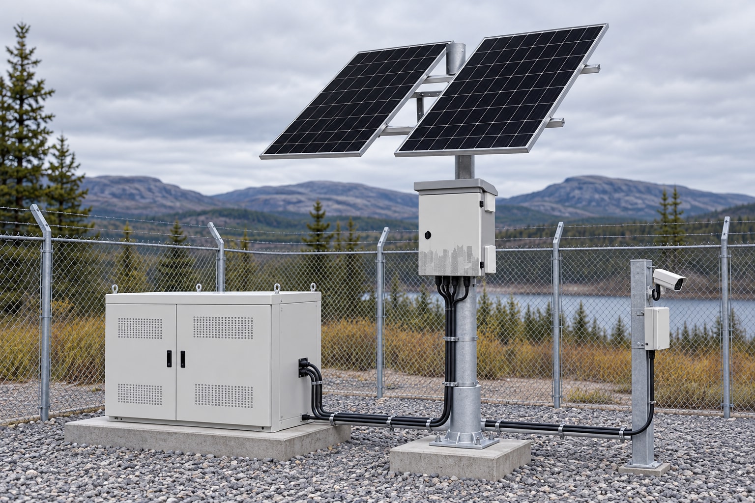
Solar Panel, Battery, MPPT and Load Calculation Guide
Use one practical worksheet to size loads, battery storage, solar panels and an MPPT controller for an off-grid system in South Africa.
By Maxsol Team

A reliable solar power system must be calculated in dependency order: establish the real load, convert it to daily energy, size the battery for the required autonomy, size the PV array for the design month, and then verify every MPPT voltage, current and charging limit.
Do not size each component in isolation. A large battery may not recharge quickly enough from an undersized array, while a suitably rated array can still damage or overload an incorrectly selected controller. The worksheet below provides a coordinated method for solar panel, battery, MPPT and load calculation.
Create the load and daily energy worksheet
Start with the equipment that must operate, not with a preferred panel or battery size. Record every camera, wireless bridge, switch, router, illuminator, sensor and auxiliary device that will draw power.
Use measured input power where possible. A device’s headline power rating may be a maximum rather than its typical consumption, but sizing from an optimistic typical figure can create an energy shortfall. For PoE equipment, include the powered-device demand and the conversion losses of the PoE source.
A practical worksheet includes:
| Load | Quantity | Input power per unit | Operating hours per day | Daily energy |
|---|---|---|---|---|
| CCTV camera | 2 | 8W | 24h | 384Wh |
| Wireless bridge | 1 | 7W | 24h | 168Wh |
| Network switch | 1 | 6W | 24h | 144Wh |
| Night illuminator | 1 | 18W | 12h | 216Wh |
| Total | 912Wh/day |
Calculate each row as:
Daily energy in Wh = quantity × input power in W × operating hours
Then add all rows:
Total load energy = sum of the daily energy for all loads
The example requires 912Wh per day before allowing for conversion, wiring and controller losses. If the loads operate through DC converters, PoE converters or an inverter, use their verified efficiencies rather than assuming that all battery energy reaches the equipment.
For an early-stage estimate, the adjusted daily energy can be calculated as:
Adjusted daily energy = load energy ÷ overall delivery efficiency
At a hypothetical 90% overall delivery efficiency:
912Wh ÷ 0.90 = 1,013Wh/day
This efficiency is only an example. A design using several voltage conversions may perform differently from a direct DC system.
Also record the peak simultaneous load. In the example, if all equipment can operate together:
Peak load = (2 × 8W) + 7W + 6W + 18W = 47W
The system outputs, wiring, protection devices and converters must support that peak continuously, as well as any start-up or transient current. For a more CCTV-specific workflow, see the guide to sizing an off-grid solar power system for CCTV.
Account for changing and intermittent loads
Check whether power demand varies because of:
- infrared illumination switching on at night;
- heaters, fans or cabinet ventilation;
- wireless transmit power and data activity;
- camera pan, tilt, zoom or wiper motors;
- PoE start-up and negotiation;
- maintenance equipment temporarily connected to the system;
- seasonal differences in operating schedules.
For devices with several operating modes, calculate each mode separately. For example:
Daily energy = daytime watts × daytime hours + night-time watts × night-time hours
This is more dependable than multiplying one average figure by 24 hours.
Size battery storage from autonomy assumptions
Battery capacity depends on daily energy, required autonomy, permitted depth of discharge, conversion losses, temperature and ageing allowance. Nominal battery watt-hours are not the same as usable delivered energy.
Use:
Required nominal battery energy = adjusted daily energy × autonomy days ÷ permitted usable fraction
Using the hypothetical 1,013Wh/day load, two days of autonomy and an 80% usable fraction:
1,013Wh × 2 ÷ 0.80 = 2,533Wh nominal battery capacity
If the selected battery is rated at 12.8V nominal:
Battery capacity in Ah = 2,533Wh ÷ 12.8V = approximately 198Ah
This does not mean that any nominal 200Ah battery will necessarily meet the requirement. Confirm:
- rated and recommended depth of discharge;
- battery-management-system current limits;
- maximum continuous and surge discharge current;
- charge-voltage and current requirements;
- low-temperature charging restrictions;
- expected capacity at the design temperature;
- low-voltage disconnect behaviour;
- end-of-life capacity assumptions;
- compatibility with the MPPT controller’s battery profile.
LiFePO4 capacity is commonly stated at nominal voltage, but output voltage changes through the discharge cycle. Loads and converters must remain stable across the complete permitted battery-voltage range, not only at 12.8V.
Choose autonomy deliberately
Autonomy is the period for which the battery is expected to operate the load without useful solar charging. It should reflect the consequences of downtime and the site’s design-month weather, rather than being selected as a generic number.
A one-day reserve may be acceptable for a non-critical device with easy access. A remote surveillance or communications site may require a longer reserve, but increasing the battery alone creates another problem: the array must have enough surplus energy to recharge it while still powering the live load.
Battery autonomy is therefore a design assumption, not a runtime promise. Actual runtime depends on load variation, battery condition, temperature, conversion losses and the low-voltage shutdown settings.
Estimate PV energy for the design month
Use plane-of-array solar irradiation for the site’s least favourable operating month, not an annual national average. Solar conditions differ materially across South Africa, and panel angle, horizon obstruction, dust, cloud cover, temperature and nearby structures can all affect production.
The initial array calculation is:
Required PV power = adjusted daily energy ÷ design-month peak-sun hours ÷ system derating factor
Assume, purely for illustration:
- adjusted load energy: 1,013Wh/day;
- design-month peak-sun hours: 4.5 hours;
- combined PV derating factor: 0.75.
The minimum array estimate is:
1,013Wh ÷ 4.5h ÷ 0.75 = approximately 300W
The 0.75 factor represents hypothetical combined losses such as module temperature, controller conversion, wiring, soiling and imperfect operating conditions. Replace it with justified project assumptions.
Add battery recovery capacity
An array sized only to match average daily consumption may maintain the system after a good day, but it can struggle to recover after the battery has supplied energy through poor weather.
Suppose the design must recover one extra day of battery energy over two suitable solar days:
Recovery energy per day = 1,013Wh ÷ 2 = 507Wh/day
Add this to the ongoing daily load:
Total daily PV target = 1,013Wh + 507Wh = 1,520Wh/day
The revised array estimate is:
1,520Wh ÷ 4.5h ÷ 0.75 = approximately 450W
This does not guarantee two-day recovery. Peak-sun hours are an energy equivalent, not a promise that the array will operate at rated power for that period. A proper design should be checked against design-month irradiation, expected weather sequences, shading and battery charge acceptance.
Evaluate the physical installation
Before finalising panel wattage, verify:
- panel orientation and tilt;
- shading at different times of day and year;
- usable mounting area;
- module ventilation and operating temperature;
- cable distance between array and controller;
- dirt, dust, bird fouling and maintenance access;
- mechanical loading and mounting requirements;
- whether series or parallel wiring is appropriate.
A small amount of persistent shade can have a disproportionate effect, particularly when modules are connected in series. The electrical string arrangement must therefore be designed alongside the physical layout.
Check MPPT voltage, current and power limits
An MPPT controller must pass several separate checks. A controller described by only its nominal battery voltage and charge-current rating is not fully specified for an array.
Verify at least:
- maximum permitted PV open-circuit voltage;
- MPPT operating-voltage range;
- maximum PV input current or short-circuit current;
- maximum controller output or battery charge current;
- permitted array wattage for the selected battery voltage;
- battery chemistry and charge-profile support;
- operating and charging temperature limits.
For a fuller controller comparison, read MPPT versus PWM for outdoor solar charging.
Cold-weather open-circuit voltage
Panel open-circuit voltage rises as cell temperature falls. The controller must withstand the highest possible cold-condition string voltage, not only the module’s standard-test-condition voltage.
A planning formula is:
Cold Voc = module Voc at STC × [1 + |Voc temperature coefficient| × (25°C − minimum cell temperature)]
Assume a module has:
- Voc at STC: 41V;
- Voc temperature coefficient: −0.28%/°C, or −0.0028/°C;
- minimum design cell temperature: −5°C.
Then:
Cold Voc = 41V × [1 + 0.0028 × (25 − (−5))]
Cold Voc = 41V × 1.084 = approximately 44.4V
For two modules in series:
String cold Voc = 2 × 44.4V = 88.8V
Allow for module tolerances and any controller manufacturer requirement rather than selecting a controller whose absolute limit is only just above the calculated value. Cold mornings can matter even in South Africa, particularly at inland or elevated sites.
MPPT operating voltage
The string voltage must also remain inside the controller’s MPPT tracking range under hot operating conditions. Panel voltage falls as cell temperature rises, so an arrangement that stays below the cold-voltage limit may still provide too little voltage for effective tracking on a hot roof or exposed pole.
Check both extremes:
- cold Voc against the controller’s absolute maximum input voltage;
- hot operating Vmp against the controller’s minimum MPPT voltage.
Use current module and controller datasheets, including temperature coefficients and string-sizing instructions.
Array current
Series-connected modules increase voltage while string current remains broadly equal to one module’s current. Parallel strings increase current.
For parallel strings:
Array Isc = module Isc × number of parallel strings
A controller or protection calculation may require an additional current factor. The correct factor depends on the controller instructions, wiring method and applicable design requirements, so do not apply an arbitrary margin without verification.
Keep PV input-current limits separate from output charge-current limits. They are measured at different voltages and are not interchangeable.
Controller charge-current limit
A rough output-current estimate is:
Controller output current ≈ array power × controller efficiency ÷ battery charging voltage
For a hypothetical 450W array, 96% controller efficiency and a 14.0V charging point:
450W × 0.96 ÷ 14.0V = approximately 30.9A
Current may be higher at a lower battery voltage, and the controller may limit output according to its own design. Confirm the manufacturer’s array-wattage and charge-current rules at the selected battery voltage.
The battery must also accept the controller’s available charge current. A larger controller is not useful if its configured charge rate exceeds the battery manufacturer’s limit.
Coordinate battery charging and load outputs
The electrical design must work as a system across the entire voltage profile. Check the battery’s maximum charge voltage, normal discharge range and low-voltage cut-off against the controller and connected loads.
A “12V” device is not necessarily designed for every voltage that can occur in a nominal 12.8V LiFePO4 system. Confirm whether each device can tolerate the highest charging voltage and continue operating near the chosen low-voltage disconnect point. If not, use a properly specified regulated converter.
Also confirm:
- maximum current per load output;
- combined output-current limit;
- connector and terminal ratings;
- fuse or breaker selection;
- cable current capacity and voltage drop;
- load-disconnect priority;
- converter and PoE output limits;
- polarity and earthing arrangements;
- surge and lightning protection requirements.
Voltage drop is particularly important on remote cameras, access points and wireless links. A long cable may deliver acceptable voltage at a light load but fall below the equipment’s input range when infrared lighting or a radio transmitter raises demand.
Calculate voltage drop using the conductor resistance, total circuit length and maximum current. Then compare the resulting load-end voltage with the device’s full permitted input range.
Compare documented systems without treating them as component recipes
Complete systems can provide useful reference points, but their components should not be treated as freely interchangeable.
The Maxsol CS12060 120W and 60Ah solar system documents a 120W monocrystalline panel, 12.8V 60Ah 768Wh LiFePO4 battery, MPPT controller and three DC12V outputs.
The Maxsol CS400150 400W and 150Ah solar system documents a 400W panel configuration using two 200W modules, a 12.8V 150Ah 1920Wh LiFePO4 battery, MPPT control and four DC12V outputs.
These are documented system examples, not custom component prescriptions and not autonomy guarantees. For either system, verify the supplied controller configuration, PV open-circuit voltage and current limits, battery charge profile, charging temperatures, protection arrangements and output ratings against the intended load.
For perspective, 768Wh and 1,920Wh are nominal battery-energy figures. Usable delivered energy will be lower once permitted discharge depth, conversion losses, voltage limits, temperature and battery protection are considered.
Stress-test and document the final design
A worksheet is not complete until it has been tested against adverse but credible conditions. At minimum, assess the following cases:
| Design case | What to verify |
|---|---|
| Highest load | Outputs, converters, wiring and battery discharge current remain within limits |
| Longest design-night operation | Battery reaches morning without crossing the shutdown threshold |
| Poor-solar sequence | Autonomy assumption covers the selected weather scenario |
| Recharge period | Array supplies the operating load and restores the planned battery deficit |
| Cold morning | Series-string Voc remains below the MPPT’s absolute input limit |
| Hot panel conditions | Vmp remains inside the MPPT tracking range |
| Low battery voltage | Loads and converters still receive an acceptable input voltage |
| Maximum solar input | Controller power and charge-current limits are not exceeded |
| Low battery temperature | Charging follows the battery’s permitted temperature conditions |
| Degraded system | Ageing, soiling and realistic losses do not create immediate failure |
Record assumptions and sources
The final design file should state:
- device quantities, measured or rated watts and operating schedules;
- peak simultaneous load and transient loads;
- daily load energy and every efficiency allowance;
- autonomy period and permitted battery depth of discharge;
- design-month irradiation source and panel orientation;
- PV derating and battery recovery assumptions;
- module Voc, Vmp, Isc, Imp and temperature coefficients;
- series and parallel module arrangement;
- controller PV voltage, current, power and charge-current limits;
- battery voltage profile, charge current and temperature limits;
- cable lengths, conductor sizes and voltage-drop results;
- protection, isolation and load-disconnect settings;
- datasheet versions and calculation date.
Avoid common sizing mistakes
The most frequent errors are:
- using watts and watt-hours as though they are the same;
- ignoring night-time load increases;
- treating nominal battery Wh as fully usable energy;
- sizing the array from annual-average sunlight;
- overlooking battery recovery after poor weather;
- checking panel wattage but not cold Voc or array Isc;
- confusing PV input current with battery charge current;
- connecting nominal 12V loads without checking their voltage range;
- ignoring cable voltage drop;
- assuming a linked system guarantees a particular runtime.
The practical next step is to complete the worksheet with verified site and load data, then compare the linked Maxsol systems against the required port count, load, cable distance, power budget, environment and any network-management requirements.