Solar PoE vs Traditional Power for Remote Sites
Compare solar PoE and grid-fed outdoor PoE for South African remote sites across distance, civil work, monitoring, resilience and lifecycle cost.
By Maxsol Team

For remote sites, neither solar PoE nor a traditional grid-fed PoE supply is automatically better. Solar PoE is usually the stronger option where extending utility power would require substantial trenching, cabling or approvals. Grid-fed outdoor PoE is often simpler where dependable AC power already exists close to the equipment. A hybrid design can be more appropriate when continuity matters and one energy source cannot provide the required resilience on its own.
A sound comparison starts with the same cameras, radios, sensors and network service objective. It must then account for peak power, operating hours, cable distance, solar conditions, battery autonomy, grid quality, maintenance access and future expansion. Comparing only the cost of a switch or solar panel will produce a misleading result.
Define the same remote-site load and service objective
Before comparing solar PoE vs traditional power for remote sites, define one common technical requirement. Otherwise, the two architectures may be sized for different workloads and cannot be evaluated fairly.
Document the following:
- Number and type of powered devices
- Normal and maximum power draw per device
- Start-up, heater, infrared or radio transmission peaks
- Required PoE voltage and power class
- Whether each load operates continuously or on a schedule
- Copper and fibre uplink requirements
- Required network throughput
- Acceptable downtime
- Required battery or UPS autonomy
- Environmental exposure and enclosure requirements
- Expected future ports and power demand
A surveillance site may draw more power at night when infrared illumination activates. A wireless bridge may have a lower average load but still need to operate continuously to preserve the communications path. Auxiliary equipment such as an LTE router, fibre converter, controller or enclosure fan must also be included.
Use measured consumption where possible. If the equipment has not yet been deployed, use manufacturer maximums and preserve a design margin. Do not size the source from nominal figures alone.
Define the service objective
The power architecture should support a clear operating target, such as:
- Continuous surveillance with no planned overnight shutdown
- Daylight-only operation
- A communications link that may enter a reduced-power mode
- A minimum number of hours after grid failure
- Several low-solar days without loss of critical loads
- Automatic recovery without a site visit
Separate critical and non-critical equipment. During an extended energy shortage, it may be acceptable to disconnect lighting or a secondary camera while retaining the primary camera and backhaul radio. This load-priority strategy can reduce the battery capacity required for essential service.
Compare energy source, conversion and distribution
Solar PoE and grid-fed PoE can power the same broad type of network load, but the energy follows a different path.
| Comparison point | Solar PoE architecture | Grid-fed outdoor PoE architecture |
|---|---|---|
| Primary energy source | Photovoltaic array | Utility AC or another local AC supply |
| Typical conversion path | PV generation to charging and storage, then DC distribution and PoE | AC supply to power conversion, then PoE distribution |
| Stored energy | Usually central to the design | Optional UPS or battery backup |
| Main sizing constraint | Solar yield, autonomy and battery operating limits | Available circuit capacity, grid reliability and backup duration |
| Monitoring priorities | PV input, battery condition, load and charging status | AC presence, UPS status, load and network status |
| Expansion impact | May require larger PV, battery, controller and enclosure capacity | May require circuit, PSU, UPS and enclosure upgrades |
| Common strength | Independence from a distant AC connection | Simpler design where suitable AC already exists |
| Common limitation | Weather-dependent generation and battery ageing | Dependence on the AC route unless backup is added |
Solar PoE conversion
A solar architecture generally collects energy from PV modules, regulates charging, stores energy in a battery and supplies the network equipment through a controlled DC path. The design must balance daily energy use against the energy that can realistically be collected and stored.
This requires more than multiplying panel wattage by daylight hours. The calculation should allow for:
- Seasonal solar variation
- Panel angle and orientation
- Local shading
- Soiling and maintenance
- Temperature effects
- Charging and conversion losses
- Battery charge and discharge limits
- Cable voltage drop
- Required autonomy
- Battery ageing
The Maxsol IOT2802SFG-S managed solar industrial PoE switch illustrates this DC-oriented architecture. Its documented context includes eight Gigabit PoE ports, two SFP ports, a 120W PoE budget, 90W BT support, PV and battery monitoring, and PV and battery input at DC22–29.2V. Ports 3–4 can be configured for 24V or 48V PoE.
Those details do not replace system design. Confirm the actual port allocation, charging limits, battery compatibility and voltage requirements of every connected device. The switch power budget also does not indicate how long a particular battery will operate the complete site.
For a wider design workflow, the guide to solar-powered PoE and off-grid networking explains the relationship between load calculation, solar collection, storage and network distribution.
Grid-fed outdoor PoE conversion
A traditional remote-site system normally brings AC power to an outdoor cabinet or enclosure, converts it to the required DC supply and distributes PoE to the field devices. If continuity is required, a UPS or battery stage is added rather than relying on the grid alone.
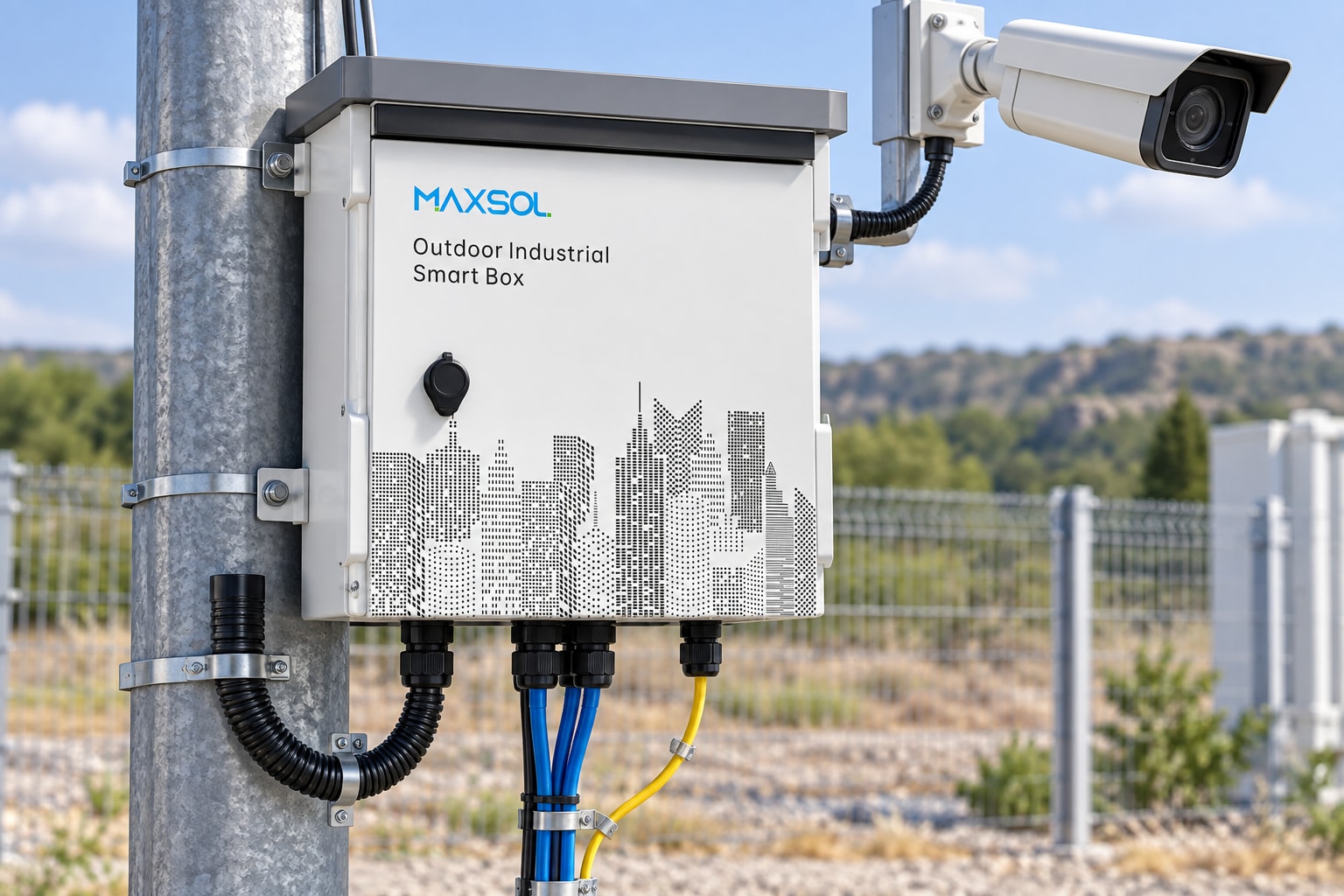
The Maxsol SBOX2802SFG-I managed industrial smart Ethernet box is an example of this approach. It is documented as an IP65 unit combining eight Gigabit PoE ports, two Gigabit SFP slots, Layer 2 management, AC100–240V input and a built-in 240W DC55V UPS module.
The presence of a UPS module does not establish backup time. Runtime depends on the connected battery arrangement, total site load, battery condition, operating temperature and configured shutdown behaviour. These values must be verified for the actual installation.
The solar and AC-fed Maxsol products are examples of different architectures, not a tested equivalent pair. Their port and power characteristics should be assessed independently against the project specification.
Evaluate installation distance and civil work
Distance often determines which option is commercially and technically practical.
If usable AC power is already available at a gatehouse, pump station, tower base or equipment room, an outdoor AC-fed PoE enclosure may require relatively little additional electrical work. Where the nearest suitable supply is far from the load, extending power can involve trenching, cable protection, distribution equipment, earthing, reinstatement and route permissions.
Solar PoE can avoid a long power trench, but it still needs:
- A secure, unshaded PV location
- A suitable support structure
- Correctly sized PV and battery cables
- A protected battery installation
- Earthing and surge-protection planning
- Safe maintenance access
- Protection against accidental damage, theft and tampering
Solar therefore removes one category of civil work; it does not eliminate installation work.
Separate the power route from the data route
A remote site still needs a communications path. Standard copper Ethernet runs are normally limited to 100 metres end to end. Installing a solar supply next to a distant camera solves the local power problem, but not necessarily the backhaul problem.
Long-distance connections may use fibre or a wireless bridge. SFP ports can support a fibre-based architecture, subject to compatible SFP modules, fibre type, connector type, distance and network design. Wireless links require suitable path clearance, mounting stability, frequency planning and capacity.
Consider the routes independently:
- How will energy reach the PoE switch?
- How will data return to the network?
- How will technicians safely access both routes?
- What happens when either route fails?
The right architecture might be solar at the endpoint with fibre backhaul, AC power with a wireless bridge, or a combination of both.
Compare the complete installation scope
For an honest comparison, include all physical work rather than only headline equipment:
Solar PoE scope
- PV modules and mounting
- Charge-control functionality
- Batteries and battery protection
- Outdoor cabinet or smart box
- PoE and network equipment
- Foundations or poles
- DC cabling and connectors
- Earthing and surge protection
- Fibre or wireless backhaul
- Security and access provisions
Grid-fed PoE scope
- AC source and circuit
- Trenching or overhead route where required
- Correctly rated electrical cable and protection
- Outdoor enclosure
- Power conversion and PoE equipment
- UPS and battery where required
- Earthing and surge protection
- Fibre or wireless backhaul
- Reinstatement and route access
A short grid extension can be simpler than a fully autonomous solar system. A long or difficult grid extension can make solar more attractive even after the array, storage and supporting structure are included.
Compare monitoring, maintenance and recovery
Remote-site availability depends on how quickly a fault can be detected, diagnosed and corrected. An architecture that operates reliably but provides no useful status information may still create expensive site visits.
Solar PoE monitoring
Useful solar-site data includes:
- PV input voltage and charging state
- Battery voltage and condition
- Current load
- Low-voltage events
- Port status
- Device connectivity
- Temperature, where the system supports it
- Historical energy trends
PV and battery monitoring can help distinguish an energy shortage from a network fault. For example, a falling battery state over several normal days may indicate increased load, shading, panel contamination, a charging issue or battery deterioration.
Monitoring does not correct inadequate sizing. Alarm thresholds and response procedures must be configured so that a technician can identify which component needs attention before travelling to the site.
Grid-fed PoE monitoring
For an AC-fed site, monitor:
- AC input presence
- UPS or battery state
- PoE port status
- Total power load
- Network uplink condition
- Repeated restarts or low-voltage events
- Surge-protection and protection-device status where observable
A UPS can bridge short interruptions, but recovery planning must also cover outages longer than the available runtime. Decide whether the system should shut down non-critical loads, use another energy source or wait for manual intervention.
The outdoor PoE switch box, fibre and battery planning guide provides a practical framework for coordinating enclosure, power, uplink and backup requirements.
Maintenance differences
Solar systems introduce PV modules and batteries as scheduled maintenance items. Panels may require inspection and cleaning, mounting hardware must remain secure, and batteries eventually require assessment and replacement.
Grid-fed systems can reduce PV-related work but do not become maintenance-free. Outdoor enclosures, UPS batteries, cable entries, seals, earthing, surge protection and electrical connections still require inspection.
For either design, prepare a recovery plan covering:
- Remote restart capability
- Spare parts and replacement compatibility
- Safe manual isolation
- Battery replacement procedure
- Configuration backups
- Escalation after repeated power events
- Site access during bad weather or after hours
The best architecture is not merely the one with fewer components. It is the one the maintenance team can monitor, reach and restore within the required service window.
Model lifecycle costs without invented prices
Lifecycle cost should be calculated from project quotations and the actual maintenance strategy. Generic prices, assumed payback periods or unsupported savings percentages are not reliable enough for site selection.
Use this structure:
Lifecycle cost = initial equipment + design and installation + civil work + energy + planned maintenance + component replacement + fault response + downtime impact + end-of-life work
Initial equipment
For solar, include the array, structure, battery, charging system, enclosure, PoE switch and protection equipment. For grid-fed PoE, include the electrical feed, enclosure, conversion equipment, PoE switch and any UPS or backup battery.
Installation and civil work
Price route surveying, trenching, foundations, cable protection, labour, access equipment, commissioning and reinstatement. This category is often decisive where the site is far from an existing supply.
Planned maintenance and replacements
Apply the project’s expected operating period. Include inspection visits, panel cleaning where required, enclosure maintenance, battery assessment and forecast replacement of finite-life components. Use supplier-confirmed service assumptions rather than a generic battery lifespan.
Fault response
Estimate the cost of a call-out, travel, access arrangements and technician time. Remote diagnosis may lower unnecessary visits, but only if the available monitoring data is integrated into the operating process.
Downtime impact
The cost of lost service varies by application. A failed convenience Wi-Fi link and a failed perimeter-security camera do not carry the same operational consequence. Record the acceptable restoration time and the cost or risk associated with exceeding it.
Expansion cost
Model at least one realistic growth case. Adding cameras or a higher-powered radio may exceed the available PoE budget, battery autonomy, PV generation or UPS runtime. An apparently cheaper installation can become costly if it has no practical expansion margin.
Do not assume that solar has free energy and therefore zero operating cost. Do not assume grid power is inexpensive merely because AC is visible nearby. Both comparisons must include the complete route, protection, backup, maintenance and recovery plan.
Select solar, grid or hybrid architecture by evidence
Use site evidence rather than a universal rule.
Choose solar PoE when
Solar PoE is likely to fit when:
- No suitable AC source exists near the load
- Extending AC requires extensive civil work
- The site has a viable, secure and largely unshaded PV position
- The load can be supported through seasonal conditions
- Adequate battery autonomy can be designed
- PV and battery maintenance is practical
- Local power monitoring is important
Reject or redesign the solar option if shading, limited mounting area, battery temperature, security exposure or sustained load makes the energy budget impractical.
Choose grid-fed outdoor PoE when
An AC-fed architecture is likely to fit when:
- A suitable supply is already close to the equipment
- The electrical route is straightforward
- The site requires higher or growing continuous loads
- Solar mounting space is restricted
- Maintenance teams are already equipped to support AC and UPS systems
- Required backup time can be met with a verified UPS and battery design
Confirm the quality and continuity of the source. “Grid available” does not necessarily mean “grid sufficient for the service objective”.
Choose a hybrid or backup architecture when
A hybrid arrangement can be justified where service continuity is more important than architectural simplicity. Possible designs include grid power with battery backup, solar with an auxiliary charging source, or separate energy paths for critical and non-critical loads.
Hybrid systems add components and control complexity, so define:
- Which source has priority
- How transfer occurs
- Whether transfer interrupts the network
- Which loads are shed first
- How batteries are charged and protected
- How failures are reported
- How technicians test each operating mode
Do not add a second source without a control philosophy. Two energy sources can still produce a single point of failure if they share an undersized battery, controller, enclosure or distribution path.
Final selection checklist
Before approval, verify:
- Measured or maximum load for every device
- Total PoE budget and per-port requirements
- Required voltage on each port
- Normal, peak and start-up consumption
- Copper, fibre and wireless distances
- SFP and fibre compatibility
- PV exposure across relevant seasons
- Battery chemistry, voltage, capacity and charging limits
- Required solar autonomy or UPS runtime
- Outdoor enclosure and environmental suitability
- Earthing and surge-protection design
- Remote monitoring and alarm functions
- Maintenance access and replacement strategy
- Expansion margin
- Complete installed and lifecycle cost
For South African remote-site projects, the practical answer is usually determined by the distance to suitable AC power, the reliability objective and the cost of maintaining the site—not by the energy source alone. Compare the linked Maxsol models against the required port count, connected load, distance, input power, environment and management functions, then validate battery, charging, backup and compatibility details for the final design.