Off-Grid PoE Design for CCTV and Wireless Networks
Plan an off-grid PoE network for cameras and wireless backhaul, covering topology, voltage matching, monitoring, night testing and recovery.
By Maxsol Team

An off-grid PoE system for CCTV and wireless networks must be designed as a complete service chain, not as a solar panel connected to a switch. The cameras, PoE interfaces, wireless backhaul, monitoring equipment, battery, controller and far-end network all need compatible voltages, sufficient simultaneous power and a defined recovery sequence.
Continuous availability should be treated as a design objective rather than a guaranteed outcome. Start by deciding which services must remain active, draw the full topology at both ends of every wireless link, verify electrical compatibility, and then test night operation, low-battery behaviour and automatic restart under realistic loads.
Define network services and availability targets
Before selecting hardware, document what the remote site is expected to do during normal operation and during an energy shortage. A farm entrance, perimeter mast, construction site or remote equipment yard may need several services, but they do not necessarily have equal priority.
A practical service definition should cover:
- Number, type and maximum power demand of cameras
- Required recording location: on-camera, local recorder or remote control room
- Live-view and playback bandwidth
- Wireless backhaul equipment at both ends
- Local access point, router or telemetry equipment
- Night-time infrared or auxiliary loads
- Environmental heating, cooling or cabinet ventilation
- Monitoring and remote-management functions
- Minimum acceptable operation during poor solar conditions
- Which loads may be disconnected to protect essential surveillance
Classify each service by operational priority:
| Priority | Typical service | Behaviour during low energy |
|---|---|---|
| Critical | Core cameras, switch management, site alarm communications | Keep operating for as long as the battery protection strategy permits |
| Important | Wireless backhaul, additional camera views | Retain where possible; shed only according to an approved operating plan |
| Deferrable | Public Wi-Fi, non-essential lighting, convenience equipment | Disconnect first |
| Recovery-only | Maintenance tools or local service ports | Enable after the core network has stabilised |
An availability target should also define acceptable interruptions. For example, must video continue locally if the wireless backhaul fails? Is a ten-minute restart acceptable after battery protection disconnects the site? Must every camera return automatically, or may an installer intervene?
“24/7” should therefore describe the intended service objective and operating strategy. It is not a universal runtime guarantee, because actual availability depends on load, weather, solar collection, battery condition, temperature, cable loss, equipment settings and maintenance.
Draw the camera, radio and backhaul topology
A topology drawing should show both power and data paths. Do not stop the diagram at the first wireless radio: the receiver at the far end also needs power, network access and a route to the recorder or monitoring platform.
A typical remote CCTV topology may be represented as follows:
- Solar panel feeds a compatible charge controller.
- The controller charges a compatible battery.
- The protected DC output supplies a voltage-compatible PoE switch.
- Switch PoE ports supply the IP cameras and near-end wireless CPE.
- The near-end CPE creates a point-to-point link to a second CPE.
- The far-end CPE connects to a separately powered switch, router or recorder network.
- Local storage retains footage when the backhaul is unavailable, if the design requires this.
- Monitoring data reports battery, solar and network status where supported.
The far end must be included in the power plan. If it is also off-grid, it needs its own energy design. If it uses utility power, determine what happens during load shedding or an extended outage. A working remote mast is of little value if the receiving radio, router or recorder has no power.
Hypothetical multi-device load example
The following is a design illustration only. Camera consumption and switch overhead are hypothetical assumptions, not measured Maxsol product performance.
| Device | Quantity | Hypothetical load per device | Simultaneous load |
|---|---|---|---|
| IP cameras | 4 | 8W | 32W |
| Near-end wireless CPE | 1 | 6.5W full-load documented value | 6.5W |
| Switch internal consumption | 1 | 8W assumed for illustration | 8W |
| Total at remote site | 46.5W |
The endpoint PoE demand in this example is 38.5W before allowing for cable loss, start-up behaviour or any additional devices. The switch’s own assumed 8W load must also be supplied by the battery system even though it is not part of the endpoint PoE budget.
For the backhaul, the Maxsol CPE295 5.8GHz wireless CPE documents a 2×2 14dBi directional MIMO antenna, one Gigabit LAN port, IEEE 802.3af/at or 9–48V DC power support, and 6.5W full-load consumption. These specifications help with interface planning, but a product range or wireless rate label does not guarantee site distance or usable application throughput. Confirm line of sight, Fresnel-zone clearance, interference, alignment and applicable local radio requirements.
Plan bandwidth as well as watts
A powered camera is not necessarily a usable camera. The backhaul must carry the aggregate video traffic under the required recording and live-view conditions.
As a hypothetical bandwidth assumption, four cameras averaging 4Mbit/s each would produce approximately 16Mbit/s of continuous video traffic. Engineering for only 16Mbit/s would leave no allowance for stream peaks, management traffic, retransmissions, playback or future devices. The designer should specify a realistic margin and verify throughput at the actual site.
Record these separately:
- Normal aggregate camera bitrate
- Expected peak bitrate
- Main-stream and sub-stream requirements
- Remote playback demand
- Management and telemetry traffic
- Link quality under adverse conditions
- Required local operation if the backhaul is lost
Do not use the radio’s headline wireless rate as the expected CCTV throughput. Confirm usable bidirectional capacity after installation.
Match switch, battery voltage and per-port interfaces
Voltage compatibility is a pass-or-fail requirement. Similar-looking DC connectors or overlapping product categories do not make two products electrically compatible.
The Maxsol CS12060 120W, 60Ah solar system documents a 120W monocrystalline panel, a 12.8V 60Ah 768Wh LiFePO4 battery, an MPPT controller and three DC12V outputs, with RS485 as an option. Its nominal 768Wh rating is not the same as usable delivered energy. Controller losses, discharge limits, temperature, cable loss and protection settings affect what reaches the load.
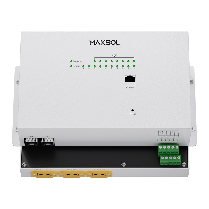
The Maxsol IOT2802SFG-S managed solar industrial PoE switch documents eight Gigabit PoE ports, two SFP ports, a 120W PoE budget, 90W BT support, PV and battery monitoring, and PV and battery input at DC22–29.2V. Ports 3–4 can be configured for 24V or 48V PoE.
These linked products are alternative architecture examples, not a tested or validated bundle. In particular, a 12.8V battery or DC12V output must not be connected directly to a switch requiring DC22–29.2V input. A designer would need to select a natively compatible battery architecture or engineer an appropriate conversion and protection stage after verifying all current, voltage, charging and fault conditions.
For every proposed combination, confirm:
- Battery nominal and operating voltage range
- Switch input voltage range
- Controller load-output voltage and current limit
- PV voltage, current and power limits
- Battery chemistry and charging profile
- Low-voltage disconnect and reconnect thresholds
- Battery charging temperature limits and protection
- Cable size, fuse rating, polarity and earthing arrangement
- PoE standard and power demand of each endpoint
- Which ports support specialised voltage modes
- Whether port configuration survives a full power loss
- Current datasheets and the supplied hardware configuration
Check each PoE port individually
A total PoE budget does not prove that every endpoint is supported. A high-power camera may exceed an individual port’s capability even when the switch has unused aggregate capacity.
Create a port schedule showing:
| Port | Connected device | Required interface | Maximum device demand | Priority | Restart order |
|---|---|---|---|---|---|
| 1 | Camera 1 | Confirm PoE standard | Datasheet value | Critical | 1 |
| 2 | Camera 2 | Confirm PoE standard | Datasheet value | Critical | 2 |
| 3 | Specialised endpoint | Confirm 24V or 48V requirement | Datasheet value | Important | 4 |
| 4 | Specialised endpoint | Confirm 24V or 48V requirement | Datasheet value | Important | 5 |
| 5 | Wireless CPE | IEEE 802.3af/at where applicable | Datasheet value | Critical | 3 |
Never apply a configurable 24V or 48V output based on connector type alone. Confirm the endpoint input specification and switch-port configuration first.
For a detailed treatment of aggregate and per-port calculations, use the PoE power-budget guide for security cameras. Include the switch’s own input demand and all non-PoE DC loads in the separate solar-energy calculation.
Plan monitoring, load priority and recovery
Remote systems need enough monitoring to distinguish between a network fault and an energy fault. At minimum, the operations team should be able to determine whether the battery is low, the switch is online, a port has failed or the wireless link is unavailable.
Useful monitoring points include:
- Battery voltage and state information supported by the selected controller
- Solar input status
- Controller alarms and protection events
- Switch input status
- Total and per-port PoE load where supported
- Port link state and error counters
- Camera reachability
- Wireless signal, noise and link-quality indicators
- Local recording health
- Time synchronisation
- Cabinet temperature where required by the design
RS485 or other telemetry may be useful, but an optional interface is not automatically a complete remote-monitoring solution. Confirm which values are available, how they are transmitted, what additional gateway is required and whether monitoring itself adds a material load.
Use deliberate load shedding
When available energy is limited, uncontrolled collapse can cause every device to cycle repeatedly. A planned load hierarchy is usually preferable.
One possible order is:
- Disconnect non-essential lighting and convenience loads.
- Disconnect secondary cameras.
- Retain core cameras and local recording.
- Retain backhaul if remote alarms or live monitoring are critical.
- Permit battery protection to disconnect the remaining system at its defined threshold.
The correct priority depends on the service. For some sites, local recording is more important than the backhaul. At others, an alarm view at a control room is the primary objective.
Managed switching can help with remote port control, diagnostics and scheduled recovery, but it adds configuration requirements. The practical differences are covered in the guide to managed and unmanaged PoE switches.
Define an accepted restart sequence
After a low-voltage shutdown, every load starting simultaneously may cause a second voltage dip. The project should define whether loads restart together, in stages or only after the battery reaches a higher recovery threshold.
A staged sequence could be:
- Controller and protection system stabilise.
- Network switch starts.
- One critical camera starts.
- Wireless backhaul starts.
- Remaining critical cameras start one at a time.
- Secondary devices start after a delay.
- The monitoring platform confirms all required services.
Test whether cameras, radios and switch settings return without manual intervention. Also confirm that any local recorder repairs its storage or recording process correctly after an abrupt shutdown.
Validate night operation and restart behaviour
Commissioning should include a full dark-period test because camera demand may rise when infrared illumination activates. Daytime testing alone can miss the highest simultaneous CCTV load.
A useful commissioning sequence is:
- Inspect the installation. Check polarity, fusing, cable glands, strain relief, enclosure sealing, earthing and device labels.
- Confirm electrical compatibility. Record battery, controller, switch and endpoint voltage ranges before energising the system.
- Start without PoE loads. Measure and record the switch input behaviour.
- Enable one port at a time. Confirm device detection, negotiated power and network connectivity.
- Apply all simultaneous loads. Include every camera, radio and auxiliary DC device expected in normal service.
- Force night mode where appropriate. Confirm the effect of infrared operation and any heater or illuminator loads.
- Run a bandwidth test. Stream and record all required cameras while checking the wireless link and far-end network.
- Interrupt the backhaul. Verify whether local recording and alarms behave as specified.
- Simulate an orderly low-energy response. Test approved load shedding and protection thresholds without bypassing battery safeguards.
- Perform a complete cold restart. Remove and restore power according to the equipment instructions, then verify automatic recovery.
- Repeat recovery with all endpoints connected. Look for boot loops, port overloads and configuration loss.
- Document the result. Record settings, observed loads, restart times and any service requiring manual action.
Solar input during a short daytime test can conceal an undersized battery or an excessive night load. Validate operation over the project’s defined night test period, but do not treat one successful night as proof of universal autonomy. Seasonal conditions, shading, contamination, temperature and future load changes still need to be considered.
Handover and maintenance checklist
A remote network is easier to support when the handover pack records the actual installed configuration rather than only the original proposal.
Include:
- Final power-and-data topology
- Device list and serial-number register
- Camera and radio locations
- Port allocation and PoE mode
- Verified voltage ranges and polarity
- Battery, controller and switch settings
- Fuse and cable specifications
- Hypothetical design assumptions replaced by commissioned readings
- Normal daytime and night-time loads
- Wireless alignment and baseline link indicators
- Camera bitrate and recording configuration
- Load-priority and shutdown sequence
- Automatic restart sequence
- Monitoring addresses and alarm thresholds
- Configuration backups
- Safe isolation procedure
- Inspection and cleaning schedule
- Battery and enclosure inspection criteria
- Process for approving additional devices
Common mistakes to prevent during maintenance include adding a camera without recalculating the PoE and energy loads, replacing a radio with a different voltage requirement, changing ports 3–4 without checking their configured output, and assuming that a nominal battery Wh rating equals usable runtime.
As a practical next step, compare the linked Maxsol examples with the project’s required port count, simultaneous load, battery and switch voltages, wireless distance, line of sight, environmental conditions and management needs. Verify the current datasheets, supplied configuration and compatibility of every component before treating them as one system.