90W PoE++ 802.3bt Switch Guide for South African Sites
Learn when a 90W PoE++ 802.3bt switch is needed, how to check ports, cabling and power budgets, and compare practical industrial options.
By Maxsol Team

A 90W PoE++ 802.3bt switch is needed when a powered device needs more power than standard PoE+ can supply, or when its installation specifically requires four-pair PoE. Typical examples include PTZ cameras with heaters, illuminators or wipers, multi-sensor cameras, high-power wireless equipment and certain access-control or edge devices.
Do not select a 90W PoE++ switch solely because a device is labelled “high power”. Confirm the device’s maximum input demand, supported PoE standard, required pin pairs, cable route and the switch’s total PoE budget. A 90W-capable port does not mean every connected device receives 90W, nor that every port on a switch necessarily supports 802.3bt.
PoE classes in practical terms
Power over Ethernet sends DC power and network data through a single Ethernet cable. In surveillance, wireless and industrial networking installations, this can reduce the need for separate power supplies at each camera, access point or field device.
The practical difference between PoE generations is the power class that the switch and powered device can negotiate.
| PoE type | Common IEEE standard | Practical use cases | Key selection point |
|---|---|---|---|
| PoE | IEEE 802.3af | Basic IP cameras, VoIP phones, simple sensors | Suitable for low-power devices |
| PoE+ | IEEE 802.3at | Standard fixed cameras, many wireless access points, some compact PTZ cameras | Confirm peak demand, not only normal operation |
| PoE++ | IEEE 802.3bt | High-power PTZ cameras, multi-sensor cameras, demanding wireless or edge equipment | Check four-pair support and total switch power budget |
IEEE ratings are often discussed as port-output ratings, while the powered device receives less after normal cable losses. This distinction matters most with 90W PoE++ 802.3bt designs. A device that needs close to its maximum power rating at the far end of a long cable run may need a larger design margin than its headline wattage suggests.
For a typical fixed camera drawing modest power, PoE+ is often adequate. Moving to PoE++ makes sense where the load rises sharply during certain operating conditions, such as night-time infrared use, motor movement, cold-start operation or activation of a heater or wiper.
Focus on peak demand, not average draw
A camera may draw far less power during daylight than it does after dark. Similarly, a wireless unit may consume more power during start-up or under peak radio activity. Use the powered device’s stated maximum power requirement as the starting point for switch selection.
Add a sensible allowance for:
- Cable-related power loss, especially on long runs.
- Start-up and inrush demand where documented by the device manufacturer.
- Environmental accessories such as heaters, blowers and illuminators.
- Future configuration changes, including added radios or camera functions.
- Simultaneous operation across several PoE ports.
Avoid estimating from an existing low reading on a power meter. It may not capture the device’s highest-load state.
When higher-power devices need 802.3bt
A 90W PoE++ 802.3bt switch is a practical choice when the powered device exceeds PoE+ capacity or explicitly calls for IEEE 802.3bt. In a project specification, this is commonly driven by the device’s maximum consumption and its need for four-pair power delivery.
High-power PTZ and outdoor surveillance cameras
PTZ cameras can need significantly more power than fixed cameras, especially when they combine pan-tilt-zoom motors with infrared lighting, integrated heating or other environmental functions. A camera’s base power requirement may look modest, but its maximum rated load can be substantially higher.
Check whether the camera requires:
- IEEE 802.3at or IEEE 802.3bt.
- Two-pair or four-pair PoE.
- A specific PoE class or input voltage range.
- Separate power for heater, wiper or illuminator functions.
- A maximum cable length lower than the usual Ethernet planning limit.
Where a camera supports an external power input as well as PoE, do not assume the lower PoE requirement covers every accessory. Read the manufacturer’s power table for the exact camera variant and environmental configuration.
Multi-sensor cameras and edge devices
Panoramic and multi-sensor cameras can combine several image sensors, analytics hardware, illuminators and on-board storage. Their load can exceed conventional PoE+ limits, particularly when all features are active.
Other devices that may justify a 90W PoE++ 802.3bt port include:
- High-capacity outdoor wireless access points.
- Multi-radio wireless equipment.
- Industrial gateways or edge computers designed for PoE input.
- Access-control equipment with higher electrical loads.
- Remote devices combining networking, sensing and control functions.
The decisive factor is not the product category. It is the specific powered-device specification, including its maximum load and supported PoE implementation.
When 90W is unnecessary
Specifying 90W across an entire installation can add cost and complicate power planning without improving the result. Standard PoE or PoE+ may be more appropriate for fixed cameras, low-power wireless bridges and simple network endpoints.
A mixed deployment is often sensible: reserve 802.3bt ports for the few demanding endpoints, and use af/at-capable ports for ordinary devices. This approach protects the power budget and leaves room for expansion.
Verify ports, pins, cable and input supply
A successful PoE++ installation depends on the whole path: the switch, cable, connectors, intermediate hardware and powered device. A 90W port alone cannot overcome unsuitable cabling, a poor termination or an undersized upstream power source.
Confirm which physical ports provide 90W
Do not assume every PoE-labelled port offers PoE++. Many switches combine ordinary PoE/PoE+ ports with a smaller number of high-power ports.
For example, the documented PS2802SFG-I-BT configuration has eight Gigabit PoE ports and two SFP ports. Ports 1–8 support IEEE 802.3af/at, while ports 1–2 support IEEE 802.3bt up to 90W. The relevant choice is therefore to place high-power endpoints on ports 1 or 2 and allocate standard powered devices to the remaining ports.
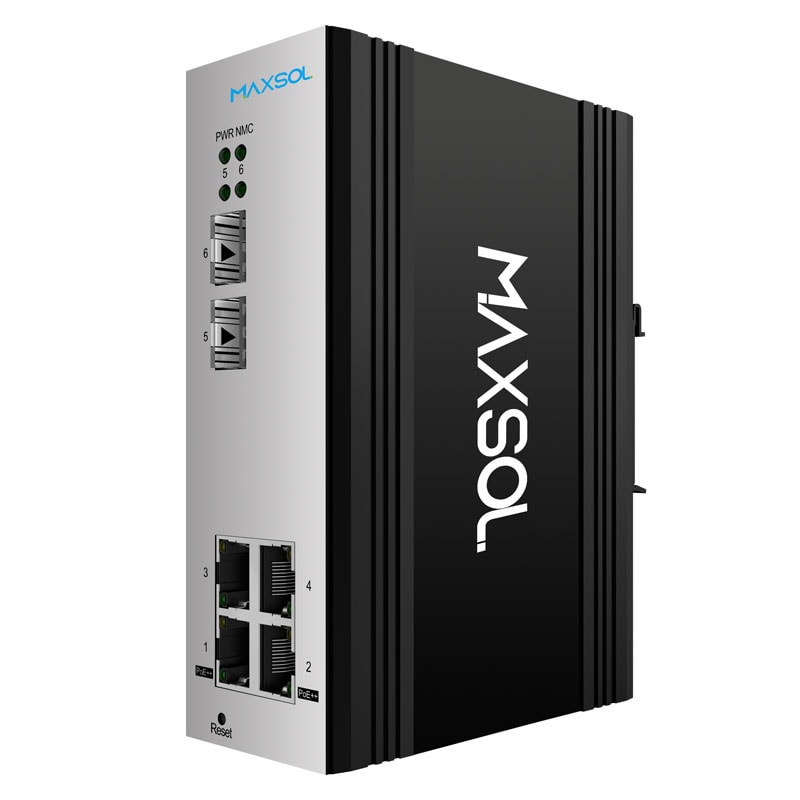
The PS2402SFG-I-BT follows the same high-power allocation principle in a smaller layout: four Gigabit PoE ports and two SFP ports, with up to 90W IEEE 802.3bt support on ports 1–2.
Document port assignments in the installation schedule. This simple step prevents a high-power camera from being connected to an af/at-only port during commissioning or future maintenance.
Verify four-pair PoE and pin compatibility
PoE++ 802.3bt uses all four twisted pairs in an Ethernet cable to deliver higher power. The cabling path must preserve all four pairs correctly from the switch to the powered device.
Before installation, verify that:
- The switch port supports the required IEEE standard.
- The powered device explicitly supports the same standard or a compatible negotiated mode.
- The Ethernet cable contains all four pairs and is correctly terminated.
- Patch panels, couplers, surge protectors and wall outlets are rated for the intended PoE application.
- No passive PoE injector, unsuitable splitter or non-standard midspan device sits in the route.
A device with an RJ45 port is not automatically compatible with 802.3bt. Likewise, a cable that carries data successfully may still be unsuitable for high-power PoE if connectors are damaged, conductors are poor quality or intermediate components are not designed for the load.
Avoid mixing standards-based PoE with passive PoE equipment unless the device documentation explicitly permits the arrangement. Passive PoE applies fixed voltage without the IEEE detection and classification process; it is not interchangeable with 802.3af, 802.3at or 802.3bt.
Assess cable condition and route length
Copper quality, conductor gauge, termination quality and route length all affect voltage drop and heat. Long outdoor cable paths deserve particular attention in South African surveillance, perimeter and wireless projects, where field equipment can be far from the communications cabinet.
Use appropriately specified solid-copper Ethernet cable for permanent runs. Be cautious with copper-clad aluminium cable, unidentified legacy cable, damaged patch leads and long chains of couplers. These can increase resistance and reduce the power available to the endpoint.
Plan around the following practical checks:
- Measure or verify the actual cable route rather than estimating from a site plan.
- Inspect outdoor terminations for moisture ingress, corrosion and strain.
- Keep high-power PoE patch leads short and in good condition.
- Check that cable bundling and enclosure conditions do not create excessive heat.
- Test the camera or device under its maximum expected operating mode after installation.
Data connectivity is not proof that power delivery is healthy. A camera may connect successfully but restart intermittently when its heater, IR LEDs or motors activate.
Size the input supply and full PoE budget
The switch’s input power source must cover the combined load of the switch itself and all powered devices, with appropriate design headroom. This is separate from the maximum available on a single port.
For each endpoint, record its maximum stated power demand. Add the totals for devices that may operate at the same time, then compare the result with the switch’s documented PoE budget and the available input supply capacity.
A simple planning calculation is:
Required PoE capacity = sum of simultaneous maximum endpoint loads + allowance for losses and headroom
Do not multiply the number of ports by 90W unless the switch documentation states that such simultaneous output is available. A switch may provide high power on selected ports while having a lower total budget across all ports.
For DC-powered industrial installations, also check:
- Input voltage range required by the switch.
- Input supply output capacity.
- Voltage drop on DC feeder wiring.
- Battery or solar-system performance at low state of charge.
- Protection, earthing and surge-control requirements for the site design.
Compare 4-port and 8-port managed options
Port count should match both the immediate endpoint total and reasonable expansion needs. For managed installations, the decision also includes uplink design and the operational value of monitoring and configuration controls.
| Consideration | 4-port managed option | 8-port managed option |
|---|---|---|
| Suitable scale | Compact cabinet, small gate, isolated equipment cluster | Larger camera group, field cabinet or growing site |
| Gigabit PoE ports | 4 | 8 |
| High-power allocation | Ports 1–2 support IEEE 802.3bt up to 90W | Ports 1–2 support IEEE 802.3bt up to 90W |
| Standard PoE support | Ports 1–4 support IEEE 802.3af/at | Ports 1–8 support IEEE 802.3af/at |
| SFP ports | 2 | 2 |
| Planning advantage | Avoids unused ports in compact deployments | Provides more ports for standard PoE endpoints beside high-power devices |
The linked 4-port managed industrial PoE switch is worth assessing where a site needs up to two high-power endpoints alongside a small number of standard PoE devices. Its four Gigabit PoE ports and two SFP ports suit compact network layouts, subject to confirmation of the complete project power budget and environmental requirements.
The 8-port managed industrial PoE switch provides eight Gigabit PoE ports and two SFP ports. It may be the more practical layout when two 90W endpoints must share a cabinet with several conventional cameras, access points or other af/at devices.
Why management can matter on a surveillance network
Managed switching can be useful where installers and network teams need visibility and control over a distributed installation. The relevant management features should be confirmed from the product documentation before selection, but the general reasons to choose a managed switch include segmenting traffic, observing port status and applying network policies.
For a camera site, management is most valuable when it helps the team identify whether a problem is related to power, link state, uplink capacity or network configuration. It does not replace correct power calculations or cable testing.
Factor in uplink capacity
High-power endpoints do not automatically create high network traffic, but high-resolution cameras and multi-radio wireless devices can. Review the expected aggregate traffic from all connected devices, then size copper or fibre uplinks accordingly.
SFP ports offer a useful physical uplink option where fibre is needed between buildings, cabinets or distant site segments. Confirm the required SFP type, fibre design and network compatibility separately; the presence of an SFP port does not determine the complete fibre solution.
Consider hardened unmanaged deployment
Not every field installation needs a managed Gigabit switch. Some projects need a simpler hardened switch with dedicated high-power ports, particularly where the endpoint count, throughput requirements and operating environment are already clearly defined.
The documented PS1802FE-HIB has eight Fast Ethernet PoE ports, one Gigabit uplink and two SFP uplinks in IP40 DIN-rail construction. Ports 3–8 support IEEE 802.3af/at, while ports 1–2 support IEEE 802.3af/at/bt up to 90W.
This layout can be relevant when two high-power endpoints need dedicated ports and the remaining attached devices are appropriate for Fast Ethernet access connections. Review the network throughput requirement carefully: Fast Ethernet access ports may be suitable for some camera designs, but they are not automatically suitable for every high-resolution, multi-sensor or bandwidth-intensive device.
Assess the hardened IP40 DIN-rail PoE switch with high-power ports against these project questions:
- Are two high-power ports sufficient?
- Are the access devices suitable for Fast Ethernet connectivity?
- Is an unmanaged design appropriate for fault finding and network control?
- Does the DIN-rail enclosure arrangement suit the cabinet layout?
- Does the overall site design address power input, heat, moisture, dust and surge exposure?
IP40 construction describes a degree of protection against solid objects; it should not be treated as a weatherproof outdoor enclosure rating. If the switch will be installed outdoors or in a harsh field environment, assess the complete cabinet, seals, cable entries, thermal conditions and protection system.
Pre-installation checklist
Use this checklist before ordering a 90W PoE++ 802.3bt switch or starting installation.
Powered-device checks
- Record the exact model number of each camera, access point or endpoint.
- Confirm its maximum, not average, power consumption.
- Confirm whether it needs IEEE 802.3af, 802.3at or 802.3bt.
- Verify whether four-pair PoE is required.
- Check demand with all accessories active, including IR, heater, wiper and motors.
- Identify whether a separate power input is required for any feature.
Switch and port checks
- Confirm the number of PoE ports required now and for planned expansion.
- Identify exactly which switch ports support up to 90W.
- Ensure high-power devices are assigned to those ports.
- Verify the total PoE budget, not only the per-port maximum.
- Confirm whether Gigabit or Fast Ethernet access ports meet endpoint bandwidth needs.
- Consider whether managed operation is needed for the project.
Cable and physical installation checks
- Use suitable four-pair copper Ethernet cabling for high-power links.
- Verify cable route lengths and inspect existing cable condition.
- Check patch panels, connectors, couplers and surge protection for PoE suitability.
- Eliminate damaged, corroded or poorly terminated components.
- Plan protection and earthing in line with the overall site electrical design.
- Confirm that outdoor equipment is housed in an appropriate enclosure.
Power-system checks
- Calculate simultaneous maximum powered-device demand.
- Include allowance for cable losses and operational headroom.
- Confirm the switch input voltage and input power requirements.
- Verify the upstream supply, battery system or solar power design can support the full load.
- Test devices during their highest-load operating conditions before handover.
Frequently asked questions
Does 802.3bt always mean 90W at the device?
No. “90W” commonly describes the power capability at the power-sourcing equipment port under the relevant 802.3bt implementation. The power available at the device is lower because cable resistance causes normal losses. Check the powered device’s required input power and the planned cable run.
Can an 802.3at device connect to a 90W PoE++ port?
In a standards-based installation, an af/at powered device can generally negotiate for the power class it requires from a compatible PoE++ port. Still confirm the specifications of both devices and avoid non-standard passive PoE equipment in the same connection path.
Can two 90W devices run from any switch with two high-power ports?
Only if the switch’s documented total PoE budget and its input supply can support both devices at their simultaneous maximum demand. Dedicated 90W ports do not by themselves confirm that the switch can deliver 180W concurrently.
Is Cat5e suitable for 90W PoE++?
Suitability depends on the actual cable construction, length, installation condition and the requirements of the equipment. A correctly installed, standards-compliant four-pair cable may be appropriate, but old, damaged, unknown or copper-clad aluminium cabling adds risk. Verify the complete cable path rather than relying on the category marking alone.
For a practical next step, compare the linked Maxsol models against your required port count, endpoint load, cable distance, input power source, installation environment and need for managed network control.