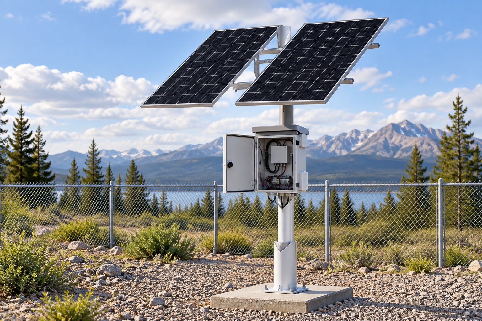
Five Key Factors for Choosing an Outdoor Solar System
Compare five key factors when choosing an outdoor solar power system: load, solar access, battery autonomy, installation and lifecycle support.
By Maxsol Team

Choosing an outdoor solar power system should begin with the equipment it must power, not the advertised panel wattage or battery capacity. The five key factors are the verified electrical load and interfaces, solar access during the design month, battery autonomy under expected temperatures, outdoor installation and maintenance requirements, and the system’s ability to expand over its useful life.
A suitable system must work as a complete power chain: solar modules, controller, battery, outputs, cabling, protection and connected devices. Buyers should therefore compare documented evidence for each factor rather than assuming that a larger panel or battery automatically guarantees reliable operation.
1. Verify the load and electrical interfaces
The first step is to establish the true continuous and peak load of every device at the site. For a CCTV or wireless network installation, this may include cameras, infrared illuminators, wireless radios, routers, switches, media converters, storage devices, heaters, fans and control equipment.
Do not rely only on the nominal rating printed on a product category or marketing sheet. Request model-specific power information and confirm it against the proposed operating configuration.
Questions to answer about the load
Document the following for every connected device:
- Input voltage and permitted voltage range
- Typical operating power
- Maximum power consumption
- Start-up, boot or inrush demand
- Day and night power differences
- Whether optional functions increase consumption
- Required operating hours per day
- Number and type of power ports
- Connector size, polarity and pin assignment
- Data interfaces and network topology
Night-time demand is particularly important for surveillance systems. A camera may consume more power when infrared illumination activates, while a pan-tilt-zoom camera can have higher peak demand when moving. Wireless equipment may also draw more power during heavy traffic or link recovery.
The total daily energy requirement is measured in watt-hours, not simply watts. As a basic screening calculation:
Daily load energy = device power in watts × operating hours
Add each device’s daily requirement, then account for conversion and cable losses. Do not treat an inverter, DC converter or PoE injector as loss-free.
For a more detailed process, use the off-grid solar sizing guide for CCTV systems after the initial supplier comparison. The purpose at this stage is to reject options with unclear or incompatible inputs and outputs before spending time on detailed calculations.
Confirm interface compatibility
Power capacity alone does not establish compatibility. A system with sufficient stored energy may still be unsuitable if its outputs cannot directly support the equipment.
Confirm:
- Whether the load needs regulated DC, passive PoE, standards-based PoE or AC
- Whether converters or injectors are included or must be added
- The maximum current available per output and across all outputs
- Whether simultaneous start-up can overload the controller or protection devices
- Whether the output voltage remains within the equipment’s permitted range
- Whether connectors are suitable for outdoor use
- How power and data cables enter the enclosure
For example, the Maxsol CS6030 60W and 384Wh solar system documents a 60W monocrystalline panel, 12.8V 30Ah 384Wh LiFePO4 battery, MPPT controller and three DC12V outputs. Those specifications make it a useful scale reference, but they do not confirm suitability for an unspecified camera or network load. The current limits, connectors, charging conditions and total energy demand still need verification.
A common buying mistake is comparing a device’s required input with the battery’s nominal voltage while ignoring the controller, output regulation and cable voltage drop. Evaluate the complete interface from the battery enclosure to the device terminals.
2. Assess design-month solar access and shading
Solar availability should be assessed for the least favourable operating period, not an annual average or a clear summer day. The design month is the period in which the site expects the weakest combination of solar production, weather and operating demand.
South Africa has substantial regional and seasonal variation. Coastal cloud, inland storms, winter sun angles, local terrain and nearby structures can all affect a site differently. A supplier should therefore use location-specific design inputs rather than presenting one solar yield assumption as valid for the whole country.
Inspect the actual installation point
A desktop estimate is useful, but it cannot reveal every obstruction. Inspect the proposed module position and record:
- The direction and tilt available for the panel
- Shading at different times of day
- Seasonal changes in the sun’s path
- Trees and vegetation that may grow into the solar window
- Buildings, poles, antenna masts and security structures
- Dust, bird fouling or salt deposits likely to reduce output
- The distance between the solar modules, controller, battery and load
- Whether future construction could create shading
Partial shading can reduce production even when most of the panel remains in sunlight. A shadow from a pole or antenna may move across the module during the day, so a single site photograph is not always enough.
Ask the supplier to identify the design-month solar input used and explain how shading losses were treated. If the proposal does not state its solar assumptions, two apparently similar systems cannot be compared fairly.
Separate panel rating from daily energy harvest
A panel’s watt rating describes output under defined conditions; it is not the amount of energy the system will collect every day. Actual harvest varies with sunlight, module temperature, orientation, shading, dirt, controller behaviour and wiring losses.
When comparing proposals, request:
- The assumed design-month solar resource
- The panel orientation and tilt assumption
- The estimated shading allowance
- Expected system losses
- The controller’s permitted solar input
- The recovery approach after extended poor weather
Avoid proposals that promise continuous operation solely from panel wattage. The panel, battery and load must be assessed together because a panel may be large enough for average conditions but unable to recharge the battery adequately during the design month.
3. Match battery autonomy, temperature and protection
Battery autonomy is the period for which stored energy can support the verified load when solar generation is insufficient. It should be selected according to site risk, expected poor-weather periods and the operational importance of the connected equipment.
There is no universal autonomy target for every outdoor system. A low-priority monitoring point with easy access may justify a different design margin from a remote security or communications site where an outage has serious consequences.
Compare usable energy, not only amp-hours
Amp-hours cannot be compared properly without voltage. Watt-hours provide a clearer energy reference:
Nominal battery energy in watt-hours = nominal voltage × amp-hours
However, nominal energy is not automatically equal to usable energy at the load. Available capacity can be affected by:
- Permitted depth of discharge
- Battery management limits
- Operating and charging temperature
- Conversion losses
- Cable losses
- Battery condition over time
- High current demand
- Controller cut-off settings
Ask suppliers to show how they derived the stated autonomy from the daily load and usable battery energy. The calculation should also explain whether it includes conversion losses and a reserve margin.
The Maxsol CS12060 120W and 768Wh solar system documents a 120W monocrystalline panel, 12.8V 60Ah 768Wh LiFePO4 battery, MPPT controller and three DC12V outputs. Its larger documented panel and battery ratings make it a different scale option from the CS6030, but neither model should be assigned a runtime without the site load and solar conditions.
Check the full temperature range
Outdoor enclosures may experience temperatures that differ considerably from the surrounding air, especially in direct sun. Battery discharge, charging and protection behaviour can also have different temperature limits.
Request the current battery and controller documentation and confirm:
- Permitted charging temperature
- Permitted discharging temperature
- Low- and high-temperature protection behaviour
- Whether charging stops or is reduced outside defined limits
- Enclosure ventilation or thermal management requirements
- The effect of the mounting position on internal temperature
- How temperature sensing is implemented
Do not assume that all LiFePO4 batteries have identical temperature limits or battery management functions. These details must be confirmed for the supplied configuration.
Protection should also be examined as a coordinated system. Ask about overcharge, over-discharge, overcurrent, short-circuit, reverse-polarity and temperature protection, while checking which functions are provided by the battery, controller or external protective devices. A list of protection terms is not enough unless the supplier explains the operating thresholds and reset process.
4. Plan outdoor mounting, cabling and maintenance
A correctly sized solar system can still fail operationally if the module shifts, water enters a connector, cable losses are excessive or maintenance staff cannot safely reach the equipment. Mechanical and service considerations should be part of procurement, not left until installation day.
Match the mounting arrangement to the site
Confirm how the solar modules, enclosure and connected equipment will be attached to the proposed pole, wall, mast or ground structure. The design should consider:
- Available mounting surface and structural condition
- Module dimensions and clearance
- Wind exposure
- Adjustment and locking of panel angle
- Enclosure orientation
- Water drainage
- Cable support and bend radius
- Tamper and theft risk
- Access for inspection and component replacement
Mounting hardware should be assessed for the actual environment. A coastal site, dusty industrial yard and protected inland compound may need different material and maintenance choices. Ask the supplier to identify the materials and finishes included rather than relying on a general description such as “outdoor grade”.
Calculate cable losses before final placement
Long DC cable runs can create voltage drop and waste energy. The required conductor size depends on current, cable length, system voltage and permitted voltage drop.
Obtain a cable schedule showing:
- Cable type and conductor size
- One-way route length
- Expected current
- Calculated voltage drop
- Connector and gland types
- Separation of power and data cables
- Earthing, bonding and surge-protection arrangements
- Responsibility for field terminations
If PoE or a DC converter is used, verify its input range at the end of the cable, not only at the source. The connected device must still receive acceptable voltage during peak demand and lower battery-voltage conditions.
Outdoor networking and security equipment can also be exposed to electrical surges. Protection measures should be designed for the complete installation, including power and data paths, and installed by appropriately qualified personnel.
Define a practical maintenance plan
Maintenance requirements affect operating cost and site reliability. Before purchase, determine how often the installation should be inspected and what staff must check.
A practical inspection plan may include:
- Cleaning solar modules when dirt materially affects collection
- Checking for new shading or vegetation growth
- Inspecting brackets, fasteners and panel alignment
- Examining cables, glands and connectors for damage
- Checking the enclosure for water, insects or excessive heat
- Reviewing controller indicators, logs or alarms where available
- Measuring load voltage and current
- Confirming battery and protection status
- Recording changes made to connected equipment
Ask whether routine tasks require proprietary tools, passwords or replacement parts. Also confirm how technicians can isolate the panel, battery and load safely during service.
5. Evaluate lifecycle support and expansion
The initial installation is only one stage of an outdoor solar system’s life. Cameras may be replaced, wireless links upgraded, analytics added or port counts increased. A system selected with no documented headroom may require major changes when the load grows.
Expansion should not mean connecting extra equipment until the system begins shutting down. Any increase in load requires a fresh check of daily energy, peak current, battery autonomy, solar recovery, controller limits, output ports, cabling and thermal conditions.
Ask what can be changed safely
Before selecting a platform, confirm:
- Maximum supported panel input for the supplied controller
- Permitted battery configuration
- Total and per-port output limits
- Availability of spare output ports
- Space for converters, injectors or network equipment
- Whether firmware or settings are required for replacement components
- Which parts are field-replaceable
- What documentation is provided for diagnosis and maintenance
- How configuration changes affect protection and thermal performance
Do not assume that a controller, battery or enclosure can accept larger components merely because they physically fit. Mixing batteries or adding panels outside the approved electrical configuration can create performance and safety problems.
The Maxsol CS400150 400W and 1920Wh solar system documents two 200W modules, a 12.8V 150Ah 1920Wh LiFePO4 battery, MPPT control and four DC12V outputs. It illustrates a larger system scale and an additional documented DC output compared with the two smaller examples. It is not automatically the correct choice for a larger project: controller limits, charging temperatures, protection, physical installation and the actual load must still be checked against the current datasheet and supplied configuration.
Compare product scales without treating them as runtime promises
| Scale example | Documented solar configuration | Documented battery | Documented outputs | What the buyer must still verify |
|---|---|---|---|---|
| CS6030 | 60W monocrystalline panel | 12.8V 30Ah, 384Wh LiFePO4 | Three DC12V outputs | Load current, autonomy, connectors, controller limits and site solar access |
| CS12060 | 120W monocrystalline panel | 12.8V 60Ah, 768Wh LiFePO4 | Three DC12V outputs | Peak demand, design-month recharge, charging temperature and installation fit |
| CS400150 | Two 200W modules, 400W total | 12.8V 150Ah, 1920Wh LiFePO4 | Four DC12V outputs | Mounting space, cable losses, protection, expansion limits and full load compatibility |
These figures help compare relative system scale, but they do not establish universal autonomy, service life or guaranteed 24/7 operation. Runtime depends on the verified load, usable battery energy, environmental conditions and solar recovery.
For surveillance-specific purchasing considerations, the guide to choosing a solar power system for outdoor security cameras covers the relationship between camera functions, power demand and site design.
Five-factor supplier comparison checklist
Use the same load schedule and site information for every supplier. Otherwise, one proposal may appear more attractive simply because it uses more optimistic assumptions.
| Factor | Questions to ask | Evidence to request | Warning signs |
|---|---|---|---|
| Verified load and interfaces | What continuous and peak load was used? Are all cameras, radios, converters and accessories included? | Device load schedule, port map, voltage ranges and loss assumptions | Sizing based only on camera count or panel wattage |
| Design-month solar access | Which month and site-specific solar input were used? How was shading treated? | Solar assumptions, site photographs, orientation, tilt and shading assessment | Annual averages with no explanation of seasonal performance |
| Battery autonomy, temperature and protection | How was usable energy calculated? What happens at temperature limits or low state of charge? | Autonomy calculation, current battery and controller data, protection behaviour | Runtime promises without load, loss or temperature assumptions |
| Outdoor installation and maintenance | How will modules, enclosure, cabling and protection be installed and serviced? | Mounting plan, cable schedule, voltage-drop calculation and maintenance instructions | Generic mounting details or no allowance for cable length and access |
| Lifecycle support and expansion | What headroom and replacement options exist? Which limits apply when the load changes? | Controller limits, output ratings, replaceable-parts information and configuration documentation | Claims that any panel, battery or additional load can be added later |
A sound procurement decision should leave a clear evidence trail: verified device loads, documented interfaces, site-specific solar assumptions, a transparent autonomy calculation, an installation plan and confirmed expansion limits. If any of these is missing, ask for it before comparing system size or commercial terms.
As a practical next step, compare the linked Maxsol scale examples against your required port count, continuous and peak load, cable distance, voltage and power needs, outdoor environment, and network management requirements. Then confirm the latest datasheet, supplied configuration, controller limits, charging temperatures and protection for the shortlisted model.