300m Long-Range PoE for IP Cameras: Planning Guide
Learn when 300m Extend mode can support longer IP camera runs, with checks for cable quality, power demand, link speed and commissioning.
By Maxsol Team

A long-range PoE switch 300m mode can be a practical way to place an IP camera beyond the usual Ethernet distance limit while carrying both data and power on one cable. It is useful for perimeter cameras, gate entrances, long warehouse runs and distributed surveillance points where adding a local power supply or intermediate cabinet is undesirable.
However, 300m is a mode capability, not an automatic result for every installation. The achievable link depends on the selected switch mode, cable quality and condition, powered-device demand, network traffic, connectors and the outdoor environment. Plan each run as a complete power-and-data path, then test it at the intended camera load.
Why standard Ethernet distance matters
A conventional copper Ethernet channel is generally designed for a maximum length of 100m. This is the familiar planning limit for a switch-to-device connection, including patch leads at both ends. Beyond that point, attenuation, noise and signal reflections can make a normal link unreliable.
For surveillance installers, this limitation often appears in real-world layouts:
- A camera at a vehicle gate is 180m from the security office.
- A perimeter fence follows a long property boundary.
- Cameras are mounted across a yard, workshop or agricultural site.
- A guardhouse, access-control point or remote building has no convenient mains power.
- The nearest network cabinet is indoors while the camera route is outdoors.
Without a long-range approach, the usual alternatives are an intermediate network cabinet, fibre with media conversion, a wireless bridge, or a local power source. Each can be appropriate, but each also adds equipment, installation work and maintenance considerations.
A long-range PoE switch is intended to extend selected copper camera connections further than the conventional 100m Ethernet planning distance. It can reduce the need for additional active equipment on an otherwise straightforward cable route. It does not remove the electrical and network constraints that make long copper runs challenging.
What 300m Extend mode changes
On a compatible long-range switch, Extend mode is designed to support a longer PoE Ethernet connection to an endpoint such as an IP camera. Rather than treating every port as a conventional short Ethernet run, the switch uses its long-range operating mode for the applicable connection.
This is why a 300m long-range PoE switch should be specified by application rather than by headline distance alone. A long perimeter camera run with modest traffic is different from a high-bandwidth multi-camera aggregation point. The longer link must still carry useful data while delivering enough power at the far end.
Before relying on Extend mode, establish these points:
-
Which ports support the mode?
Some switches apply long-range operation to selected access ports or through a switch setting. Confirm the specific product documentation and port behaviour before finalising the design. -
What link rate is available in long-range operation?
Long-range modes may operate differently from ordinary Ethernet ports. Check that the actual negotiated link rate is suitable for the camera’s stream, live view requirements and any other traffic sharing the uplink. -
What is the realistic cable route length?
Measure the installed route, not the straight-line distance on a site plan. Include vertical rises, cabinet routing, service loops and patch leads. -
Is the camera’s full operating load understood?
A fixed daytime camera may draw far less than a PTZ camera, an illuminator-equipped camera or a model operating with heaters, fans or infrared lighting active. -
What happens at the network edge?
The switch-to-NVR or switch-to-core link needs enough capacity for the total camera traffic. Extending individual camera runs does not increase the bandwidth of a congested uplink.
A 300m mode is particularly relevant where the installation needs a single cable route for a camera and there is no need to carry high-throughput data from that endpoint. It should not be treated as a substitute for fibre on every long-distance or high-bandwidth project.
Long range is not the same as an uplink extension
A common design error is to see “300m” and assume that any switch-to-switch, uplink or backbone connection can be extended to that distance. In practice, distinguish the camera-facing PoE ports from the uplink ports and confirm the applicable operating mode.
For larger sites, fibre or another suitable backbone technology may still be the better choice between buildings or cabinets, while long-range PoE is used for the final camera spur.
Cable and powered-device checks
The cable is part of the system, not merely an accessory. A switch may support a 300m mode, but poor cable construction, damaged conductors, water ingress and weak terminations can undermine both data transmission and PoE delivery.
Start with the cable route and conductor quality
For a long outdoor camera run, assess the installed cable rather than assuming the category marking tells the full story. Solid copper network cable is generally preferable to copper-clad aluminium (CCA) for PoE applications because power delivery depends on conductor resistance. Higher resistance increases voltage drop and heat.
Check the following before installation or fault-finding:
- Use cable suitable for the planned environment and route.
- Avoid CCA where reliable PoE delivery is required.
- Keep joins to a minimum; each join adds a possible point of resistance, corrosion or signal loss.
- Protect outdoor cable and connection points from UV exposure, moisture and physical damage where required.
- Maintain sensible separation from sources of electrical interference.
- Avoid crushing, sharp bends and excessive pulling tension.
- Terminate all pairs correctly and consistently.
- Include patch leads in the total route length and quality assessment.
A cable tester can identify basic continuity and wire-map faults, but a simple tester does not prove that a 300m PoE camera link will be stable under load. The final check must include the actual camera transmitting video, using its expected features and receiving PoE from the installed switch.
Calculate for worst-case camera operation
Do not size a PoE system using a camera’s lowest listed power draw. Cameras can consume more power when infrared LEDs switch on, a PTZ motor moves, an illuminator activates, or environmental accessories operate.
For each powered device, record:
- Normal running power
- Maximum stated power requirement
- PoE class or required input method
- Whether it has infrared, white-light illumination, heating, cooling or PTZ functions
- Expected operating schedule and simultaneous peak conditions
- Required network throughput and video settings
Then compare the combined maximum or properly justified coincident load with the switch’s available PoE budget. Leave a sensible design margin for uncertainty and future changes rather than treating the published budget as a target to reach exactly.
Check the camera before assuming Hi-PoE is needed
Hi-PoE ports can be useful for higher-demand devices, but a 60W-capable port does not mean every connected device receives 60W. The powered device must be designed to request and accept the relevant PoE power arrangement, and the switch must have sufficient overall budget available.
Equally, a camera that needs only ordinary PoE does not benefit simply because it is connected to a higher-power port. Allocate higher-power-capable ports to devices that genuinely require them, and keep a record of that allocation for commissioning and future maintenance.
Consider outdoor electrical protection separately
Long copper cables connected to outdoor equipment can be exposed to electrical disturbances. Earthing, surge protection, cable entry practices and enclosure design should form part of the overall site design. The correct protection arrangement depends on the equipment, cabling route and site conditions, so verify the requirements for the specific installation rather than assuming the switch alone addresses them.
Compare 4, 8, 16 and 24-port options
Port count is only the first selection criterion. Compare the number of camera-facing PoE ports, uplink arrangement, total PoE budget and which ports can supply up to 60W. This helps prevent a design that has enough ports on paper but not enough power or appropriate uplink capacity.
| Model | PoE access ports | Uplinks | PoE budget | Ports with up to 60W capability | Best suited to |
|---|---|---|---|---|---|
| PS1402E | 4 Fast Ethernet PoE | 2 Fast Ethernet | 65W | Port 4 | Small camera groups and compact edge installations |
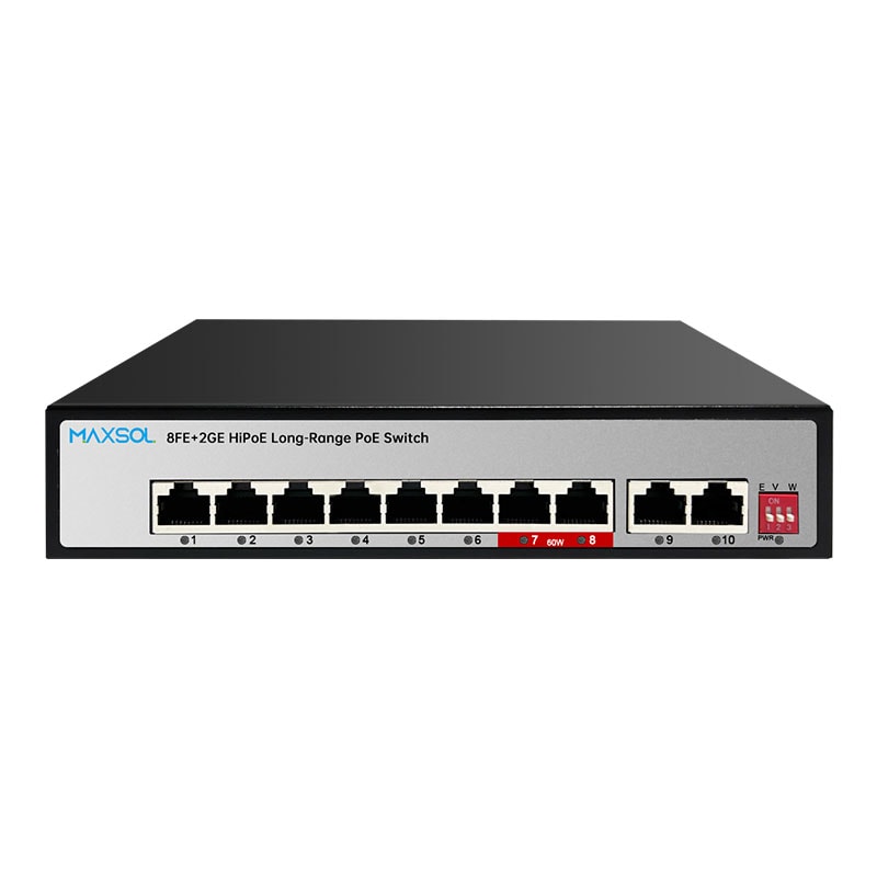
| PS1802GE | 8 Fast Ethernet PoE | 2 Gigabit | 120W | Ports 7–8 | Small-to-medium camera groups needing Gigabit uplinks |
| PS11602FE | 16 Fast Ethernet PoE | 2 Gigabit + 1 SFP | 200W | Ports 13–16 | Larger access-layer camera deployments |
| PS12402FE | 24 Fast Ethernet PoE | 2 Gigabit + 1 SFP | 300W | Ports 20–24 | Higher-density surveillance and multi-device projects |
For a compact installation with a few cameras, the PS1402E 4-port 300m long-range PoE switch provides four Fast Ethernet PoE ports, two Fast Ethernet uplinks, a 65W PoE budget, 300m long-range mode, VLAN and watchdog functions. Port 4 supports up to 60W, subject to the device requirement and available switch budget.
Where more cameras are required and the upstream network benefits from Gigabit connectivity, consider the PS1802GE 8-port 300m PoE switch. It has eight Fast Ethernet PoE ports, two Gigabit uplinks and a 120W PoE budget. Its ports 7 and 8 can provide up to 60W each, while the total budget remains the limit for all connected devices combined.
For a larger camera group or a cabinet serving several site zones, the PS11602FE 16-port long-range PoE switch combines 16 Fast Ethernet PoE ports with two Gigabit and one SFP uplink, alongside a 200W PoE budget. Ports 13 to 16 are the ports specified for up to 60W capability.
The PS12402FE 24-port 300m long-range PoE switch is the higher-density option in this group, with 24 Fast Ethernet PoE ports, two Gigabit and one SFP uplink, and a 300W total budget. Its ports 20 to 24 can provide up to 60W each.
Select the uplink for the actual aggregation load
Fast Ethernet access ports can be appropriate for individual camera connections, but the combined traffic from multiple cameras reaches the uplink together. Estimate the total expected bit rate, including peaks caused by motion, higher image complexity, remote viewing and recording overhead.
Gigabit uplinks are generally more suitable where several cameras aggregate at one switch. An SFP uplink can be useful when the wider network design requires an optical or modular uplink arrangement, but confirm the relevant transceiver, fibre type and network compatibility separately.
Hi-PoE port allocation and power budgets
A switch power budget is shared across all PoE ports. It is not a promise that every port can simultaneously deliver its maximum possible per-port value.
For example, a switch with a 120W budget and two ports capable of up to 60W cannot be assumed to supply 60W to both high-power devices while also powering several additional cameras. The combined allocation must remain within 120W, allowing for the actual demands of the other ports.
Use this practical allocation process:
- List every planned powered device and its maximum power draw.
- Mark devices that may need up to 60W capability.
- Assign those devices only to the stated higher-power ports.
- Add the maximum device loads together.
- Compare the total with the switch PoE budget.
- Retain headroom for startup variation, low-temperature operation where relevant and future additions.
- Check what the switch does if demand exceeds the budget, according to its documentation.
The specified higher-power port ranges are important during installation:
- PS1402E: port 4
- PS1802GE: ports 7–8
- PS11602FE: ports 13–16
- PS12402FE: ports 20–24
Label these ports in the cabinet schedule. This avoids a technician later moving a high-demand camera to a standard port during maintenance and creating an avoidable fault.
Avoid these PoE planning mistakes
- Adding camera wattages based only on typical daytime consumption.
- Treating a total PoE budget as a per-port rating.
- Connecting a high-demand device to an unsuitable access port.
- Forgetting that long cable resistance affects power available at the far end.
- Assuming a camera with an external accessory has the same load as the camera body alone.
- Leaving no budget margin for expansion or operational peaks.
- Failing to test infrared, PTZ movement and lighting functions after dark.
Commissioning checklist
Commissioning is where a long-range design becomes an operational installation. Test the complete installed route, rather than relying solely on a bench test with a short patch cable.
Before power-up
- Confirm the cable route length, including patch leads and service loops.
- Inspect cable for damage, sharp bends, poor joints and unsuitable outdoor exposure.
- Verify terminations, pair continuity and labelling at both ends.
- Confirm that the intended port supports the required long-range mode.
- Confirm high-demand devices are connected to the appropriate Hi-PoE-capable ports.
- Check the planned total PoE load against the switch budget.
- Review earthing, surge protection and enclosure arrangements for the site.
During functional testing
- Enable and verify the intended long-range operating mode according to the switch documentation.
- Confirm the camera powers on and remains powered.
- Verify the negotiated link and stable network connectivity.
- View live video at the recording or monitoring point.
- Check the stream at the configured resolution, frame rate and bit rate.
- Test camera functions that increase demand, including infrared, white light, PTZ movement or other installed features.
- Check for image drop-outs, packet loss symptoms, reboots or intermittent links.
- Test all cameras operating simultaneously, not one at a time.
- Check uplink performance while all planned streams are active.
Record the installed baseline
Keep a simple commissioning record for every camera: cable route identifier, approximate route length, switch and port number, camera model, expected maximum power draw, operating mode, uplink destination and test outcome. This makes later fault-finding much faster, especially where an installer is not the person maintaining the site.
A long-range PoE switch 300m design is most successful when distance, cable quality, endpoint power and video traffic are considered together. Compare the linked Maxsol models against your required port count, camera load, route distances, power budget, outdoor environment and uplink or management requirements before specifying the final switch.