Choose a PoE Switch for IP Camera Systems in South Africa
Select a PoE switch for IP cameras by calculating power, ports, uplinks, cable distance and expansion capacity for your surveillance site.
By Maxsol Team

The right PoE switch for IP camera systems has enough powered ports for the current layout, sufficient PoE budget for every camera at its maximum draw, and uplinks that will not create a traffic bottleneck. It should also suit the longest cable runs, recorder location, future camera additions and the site’s power-resilience plan.
For South African surveillance projects, start with the camera plan rather than the switch size. Count fixed and PTZ cameras separately, map where cables terminate, calculate worst-case power demand, and allow practical headroom. This prevents a common mistake: choosing a switch with enough ports but not enough usable power or uplink capacity.
Start with camera count and topology
Begin with a simple site drawing showing every camera, its cable route, the network cabinet or field enclosure, and the NVR, server or wider network connection. The drawing should identify whether all cameras return to one central switch or whether smaller access switches feed a central aggregation point.
Count ports with room to grow
One IP camera normally needs one PoE port, but the switch port count should not exactly match the current camera count. Leave spare ports for:
- Cameras planned for a later project phase
- An additional entrance, perimeter or vehicle camera
- Temporary cameras during investigations or construction
- Replacing a failed camera without immediately redesigning the cabinet
- Other PoE devices where appropriate, such as approved network equipment
For example, an eight-camera installation may fit an 8-port PoE switch today, but it has no spare powered ports. If expansion is expected, a 16-port model can be a more practical starting point than adding another switch soon afterwards.
Match the switch layout to the physical topology
A centralised topology places the PoE switch and recorder in one secure equipment room. It is straightforward to manage, but every camera must remain within the supported copper link distance or use an appropriate extension or fibre design.
A distributed topology places an access switch nearer to a cluster of cameras, such as at a gatehouse, warehouse edge or separate building. Uplinks then return to the recording network. This can reduce long copper runs, but it adds requirements for enclosure design, power protection, earthing and a reliable backhaul.
For outdoor and large-site work, assess these questions before selecting a PoE switch:
- Where will the switch be installed: a controlled cabinet, an outdoor enclosure or a remote building?
- Which cameras are close enough for standard Ethernet copper cabling?
- Does the uplink cross between buildings or run near areas with electrical interference?
- Is fibre preferable for the uplink because of route length, electrical separation or site design?
- How will the switch and upstream recorder network remain powered during planned or unplanned mains interruptions?
In areas affected by load shedding or inconsistent mains supply, camera uptime depends on more than the PoE switch. Size the upstream UPS, battery system or other backup source for the switch, recorder, network gateway and any other essential equipment—not just the cameras.
Calculate the PoE load
The PoE budget is the total power a switch can supply across all PoE ports. It is not the same as port count. A 16-port switch may connect 16 cameras physically, yet the project can still exceed its power budget if too many cameras draw high power at the same time.
Use each camera’s specified maximum power consumption, then add the figures together. Do not base the calculation only on a camera’s typical daytime draw.
Use maximum demand, not the average
Camera power use can increase when features operate simultaneously, including:
- Infrared illumination after dark
- Motorised zoom, pan and tilt movement
- Built-in heaters or blowers, where fitted
- White-light illumination
- Audio, alarms or other attached accessories
- Camera start-up or changing operating modes
A practical calculation looks like this:
| Item | Quantity | Maximum power per unit | Planned load |
|---|---|---|---|
| Fixed IP cameras | 10 | 8W | 80W |
| IR cameras | 4 | 14W | 56W |
| PTZ cameras | 2 | 25W | 50W |
| Total camera requirement | 16 | 186W |
The switch selected should support this calculated total while retaining a sensible reserve. A reserve of roughly 20–30% is often useful for temperature effects, start-up demand, small additions and avoiding operation at the limit. The right margin depends on the design, the importance of uninterrupted recording and whether camera loads can rise at night.
Also check power at the switch end and at the camera end. Cable length and cable quality can affect available PoE power, especially on long routes. Confirm the camera’s PoE requirement, the switch’s supported PoE capability and the permitted cable length for the intended installation.
Avoid two frequent power-budget errors
Adding the number printed beside each PoE port. A stated per-port maximum does not mean every port can necessarily supply that maximum simultaneously. The total PoE budget remains the controlling figure.
Assuming every camera has the same load. A compact indoor fixed camera and an outdoor PTZ with illumination can have very different maximum demand. Build the calculation from the actual camera data sheets.
Choose copper and SFP uplinks
Uplinks carry aggregated video traffic from the PoE switch to the NVR, recording server, core switch or another network cabinet. The choice between copper RJ45 and SFP uplinks should follow cable route, distance, installed infrastructure and the need for electrical separation.
When Gigabit RJ45 uplinks suit the design
Copper Gigabit uplinks can be practical where the recorder or aggregation switch is nearby, the route stays within standard Ethernet limits, and a suitable structured-cabling system is already available.
They are commonly appropriate for compact camera systems in a single office, retail premises, workshop, school block or warehouse area. However, the uplink needs to carry the combined traffic from every active camera, not merely one camera’s stream.
Estimate aggregate video traffic using each camera’s configured bitrate, then add a margin for bitrate changes, live viewing, camera traffic peaks and other network use. Do not assume a nominal camera resolution alone tells you its actual network load; codec, frame rate, scene complexity and recording settings matter.
When SFP uplinks are the better fit
SFP uplinks are useful where fibre is planned or already installed. Fibre can be especially suitable for longer inter-building links, electrical separation between buildings, and routes where a copper uplink is not the best engineering choice.
Before specifying an SFP connection, verify:
- Whether the fibre is single-mode or multimode
- Fibre connector type and available cores
- Link distance required
- The compatible SFP module type for both ends
- Uplink speed and port compatibility
- Patch-panel, splice and testing arrangements
Do not buy SFP modules based only on connector appearance. The transceivers at both ends must be compatible with the fibre type, wavelength and required link design.
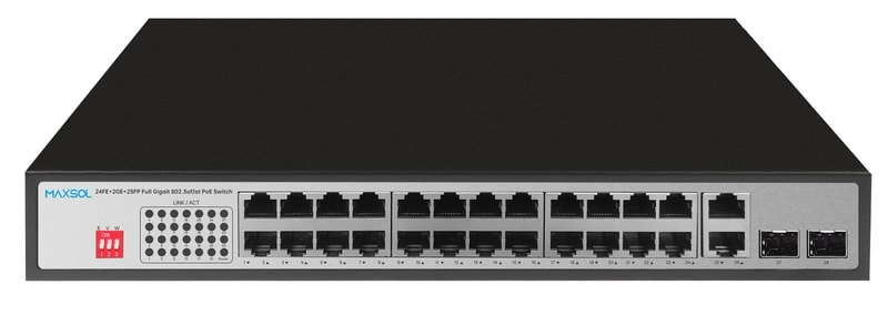
For sites that need both local copper interconnection and fibre options, the 24-port Gigabit PoE switch with RJ45 and SFP uplinks provides 2 Gigabit RJ45 uplinks plus 2 Gigabit SFP uplinks. That combination can be useful where the recording equipment is local now but a fibre backhaul is planned for a later phase.
Decide whether 300m Extend mode is needed
Standard Ethernet copper runs are typically planned around the usual 100 m channel limit. Where a camera is substantially farther away, do not simply install an overlength cable and hope it works. Assess the route, power requirement, data requirement and alternative network layout.
Extend mode may be relevant for long, lower-bandwidth camera runs where the switch and camera support the intended mode. The trade-off is important: extended-distance operation can reduce available data throughput. It is therefore not automatically suitable for every high-bitrate camera, multi-camera link or application needing normal Gigabit performance.
Ask these questions before relying on an extended-distance mode:
- Is the camera’s required video bitrate within the available extended-mode throughput?
- Does the camera require a higher PoE load than the long cable can reliably deliver?
- Is the cable solid copper, correctly terminated and suitable for the environment?
- Does the route run outdoors, near power cabling or through an area with lightning exposure?
- Would a remote PoE switch with fibre backhaul be a better long-term design?
The PS1802G 8-port Gigabit PoE switch has 300 m Extend mode, alongside 8 Gigabit PoE ports, 2 Gigabit RJ45 uplinks and a 120W PoE budget. The PS11602G also includes Extend mode, but installers should confirm its applicable distance, throughput and port-operation conditions from the relevant product documentation before designing a long link around it.
For exposed outdoor routes, include suitable surge and power protection in the overall system design. Extend mode does not replace sound cable installation, protection measures, proper earthing or a realistic assessment of site conditions.
Compare the approved 8, 16, 24 and 48-port models
The following comparison is a starting point for aligning switch size with a surveillance design. It does not make one model the best choice for every IP camera installation: camera load, backhaul design and expansion plans still determine the correct option.
| Model | PoE ports | Uplinks | PoE budget / power information | Other approved information | Best considered for |
|---|---|---|---|---|---|
| PS1802G | 8 Gigabit PoE ports | 2 Gigabit RJ45 | 120W PoE budget | 300m Extend mode, VLAN isolation and AI PoE watchdog | Smaller camera groups where power calculations remain within 120W |
| PS11602G | 16 Gigabit PoE ports | 2 Gigabit uplinks | 300W internal power supply | Watchdog, VLAN and Extend modes | Medium systems requiring more ports and greater available power planning |
| PS12402FG | 24 Gigabit PoE ports | 2 Gigabit RJ45 and 2 Gigabit SFP | 300W budget; up to 30W per PoE port | — | Larger camera groups needing both copper and fibre uplink choices |
| PS14802SFG | 48 Gigabit PoE ports | 2 Gigabit SFP | 400W budget | 100Gbps switching capacity | High-port-count designs with fibre-oriented uplink planning |
8-port: compact systems with a defined power load
The PS1802G is worth considering where eight powered camera connections are sufficient and the combined maximum camera demand fits within its 120W PoE budget. Its two Gigabit RJ45 uplinks support connection to the recording or wider network.
VLAN isolation can assist with separating connected ports in the relevant operating mode, while an AI PoE watchdog is intended to help address an unresponsive PoE device. These features should not be treated as a substitute for checking network architecture, camera configuration and physical cabling faults.
Its 300 m Extend mode makes it a model to assess for specific long-camera-run designs. Confirm the impact on throughput and camera operation before selecting it for an extended route.
16-port: more camera connections and a 300W supply
For a system that requires up to 16 Gigabit PoE camera ports, the PS11602G 16-port Gigabit PoE switch provides two Gigabit uplinks and a 300W internal power supply.
It includes watchdog, VLAN and Extend modes. It can suit a growing medium-sized surveillance layout, provided the total maximum draw is calculated against the available power arrangement and the uplink capacity is suitable for the combined camera traffic. Verify the operational details of each mode before making it part of a security-system specification.
24-port: copper plus fibre uplink flexibility
The PS12402FG has 24 Gigabit PoE ports, a 300W budget and up to 30W per PoE port. Its two Gigabit RJ45 and two Gigabit SFP uplinks offer more connection options than a copper-only uplink design.
This can be a sound fit for sites that need 24 camera connections but also need a planned fibre path to another building, a control room or an aggregation point. Remember that up to 30W per port is a per-port figure; confirm the summed load remains within the 300W budget.
48-port: centralised, high-density camera installations
The PS14802SFG 48-port Gigabit PoE switch offers 48 Gigabit PoE ports, two Gigabit SFP uplinks, a 400W PoE budget and 100Gbps switching capacity.
It is a model to examine for high-density camera deployments where many camera cables terminate in one cabinet and fibre uplinks align with the overall network plan. A 48-port chassis does not remove the need for a careful PoE calculation: 48 connected cameras can exceed 400W if their maximum combined power demand is too high. Consider splitting cameras across switches or revising the architecture where resilience, physical layout or power demand calls for it.
Management, isolation and recovery requirements
Do not assume a PoE switch is fully managed simply because it provides VLAN isolation or a watchdog feature. These functions can be valuable, but they are different from comprehensive network management capabilities.
If the project needs functions such as remote configuration, detailed traffic monitoring, port-by-port policy control, network-wide VLAN design, link aggregation or centralised fault diagnosis, define those requirements before purchasing. Confirm them against the exact switch documentation rather than relying on a general product category label.
For a straightforward dedicated CCTV network, the design may prioritise reliable physical layout, appropriate PoE capacity and a correctly sized uplink over advanced management. For a surveillance network sharing infrastructure with business systems, stronger segmentation and management requirements may be justified.
A sensible design also considers what happens after a camera stops responding:
- First check the camera’s power draw and network reachability.
- Inspect connectors, cable damage and environmental exposure.
- Confirm recorder-side settings and IP addressing.
- Consider watchdog functionality as one recovery tool, not a diagnosis of the root cause.
- Keep the camera network logically separated from unrelated traffic where the design requires it.
Plan expansion without oversizing blindly
A switch should accommodate realistic growth, but the largest port count is not automatically the best value or the most resilient layout. Expansion planning should balance spare ports, PoE budget, cabinet space, power backup and uplink design.
A useful rule is to document three numbers:
- Current connected cameras
- Approved near-term additions
- Maximum camera count expected for the site
Then calculate PoE demand for the third figure, not only the first. If the full future deployment would leave almost no power headroom, consider a larger budget, a second switch or a distributed design.
For example, a 24-camera project with two planned PTZ cameras may be better assessed against a 26-camera power calculation. If ports are scarce but power is ample, adding another access switch may work. If power is the constraint, simply adding a passive network device will not solve the issue.
Final deployment checklist
Before ordering or installing a PoE switch for IP camera systems, confirm the following:
- Camera count, including realistic future additions
- Maximum power draw for every camera, including night-time and PTZ conditions
- Total calculated PoE load with a suitable design reserve
- Number of required PoE ports and spare ports
- Required uplink type: RJ45, SFP or both
- Aggregate video traffic and the capacity of the uplink path to the recorder
- Standard cable lengths and any camera routes requiring Extend mode or a different topology
- Cable quality, termination, environmental protection and earthing approach
- Upstream backup power requirements for the switch, NVR and network equipment
- Whether VLAN isolation is sufficient or full management functions are required
- Cabinet space, ventilation and physical security requirements
- Compatibility of cameras, PoE requirements, SFP modules and recording network equipment
Compare the linked Maxsol 8-, 16-, 24- and 48-port models against your actual port count, calculated load, cable distances, uplink route, site power design and management requirements before finalising the specification.