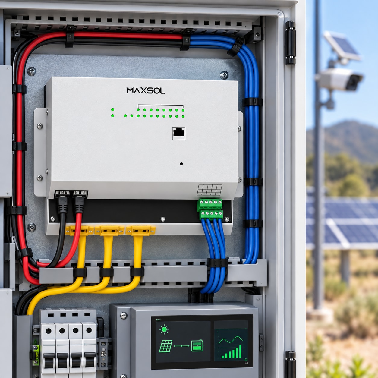
How to Engineer a 24/7 Solar Network for Remote Sites
Plan a reliable remote solar network by sizing loads, battery storage, PV recovery, managed PoE, wireless backhaul, monitoring and maintenance.
By Maxsol Team

A 24/7 solar powered network for remote locations must be designed as a complete energy, communications and maintenance system. Continuous operation cannot be guaranteed by selecting a large panel or battery alone. The design has to account for every load, the weakest solar month, battery limits, recharge time, PoE priorities, radio conditions, fault recovery and access for maintenance.
Start by defining which services must remain available and for how long the site must operate through poor solar conditions. Then calculate usable delivered energy rather than relying on nominal battery capacity. The final design should be validated under a documented worst-month test scenario before handover.
Define network services and an availability objective
“24/7” should be an engineering objective with stated limits, not an unconditional product promise. Before choosing equipment, define what the remote site does and what level of service it needs to maintain.
A surveillance and communications site might include:
- IP cameras and their night-time infrared functions
- A managed PoE switch
- A wireless backhaul or point-to-point bridge
- An edge recorder or gateway
- Environmental or security sensors
- A cellular router used for backup or management
- Cabinet ventilation, heating or cooling
- Lighting used during service visits
- Battery, solar-controller and network monitoring devices
Separate critical services from important but deferrable services. For example, a backhaul radio and perimeter cameras may be critical, while auxiliary lighting or a secondary camera group could be switched off when stored energy falls below a defined threshold.
The availability objective should answer practical questions:
- Which devices must never be deliberately disconnected?
- Which loads may be shed during an energy shortage?
- How many low-solar days must the battery support?
- How quickly should the system recover after the battery reaches its protection threshold?
- What loss of visibility or recording is acceptable during maintenance?
- Who receives alarms, and who is responsible for attending the site?
Avoid defining the objective only as an annual uptime percentage. That figure does not tell an installer how the site should behave during several overcast days, a failed panel connection or an unexpectedly high night-time load.
Inventory continuous, intermittent and startup loads
Build the load schedule from measured or verified input power wherever possible. Nameplate maximums are useful for protection and worst-case checks, but average consumption may need to be measured under representative operating conditions.
Classify each load according to its behaviour:
| Load type | Typical examples | What to record |
|---|---|---|
| Continuous | PoE switch, backhaul radio, router | Normal watts, maximum watts and 24-hour energy |
| Scheduled | Lighting, periodic uploads, auxiliary radios | Watts, operating hours and schedule |
| Event-driven | PTZ movement, heater, alarm beacon | Event power, duration and expected frequency |
| Day/night variable | Cameras with infrared illumination | Day power, night power and seasonal night duration |
| Startup or surge | Radios, motors, cabinet fans | Peak current, duration and restart behaviour |
| Conversion overhead | DC converters, injectors, inverter | Efficiency across the actual load range |
For each device, calculate daily energy:
Daily energy in watt-hours = power in watts × operating hours
For variable loads, calculate each operating state separately. A camera that consumes different power during the day and at night should not be represented by one convenient average unless that average has been measured over a suitable cycle.
Check both energy and peak power
A design can have enough daily watt-hours but still fail when several devices start together. Check:
- Total steady DC demand
- Maximum simultaneous PoE demand
- Startup or inrush current
- Converter and controller current limits
- Switch port limits and total PoE budget
- Cable voltage drop at the furthest device
- Battery voltage during a high-current event
- Restart behaviour after a low-voltage shutdown
Include cabinet equipment that is easily overlooked. Fans, heaters, media converters, fibre modules and DC-DC converters all consume energy. Small continuous loads can add materially to the daily requirement because they operate for 24 hours.
For a more camera-specific architecture, the solar PoE switch guide for remote IP camera networks explains how power distribution and network topology interact.
Size worst-month storage, solar and recharge capacity
Solar sizing should use conditions for the actual site and the least favourable operational period, not an annual average. In South Africa, seasonal sunlight, extended cloudy weather, high module temperature, dust, shading and site orientation can all affect delivered energy. Obtain suitable site-specific solar data rather than assuming that conditions at another project will apply.
Distinguish nominal energy from usable delivered energy
A battery’s nominal watt-hour rating is not the amount of energy that reaches the network equipment.
Usable delivered energy is reduced by factors such as:
- Permitted depth of discharge
- Battery-management protection thresholds
- Battery voltage under load
- DC conversion losses
- Inverter losses, if AC equipment is used
- Controller losses
- Cable and connector voltage drop
- Temperature-related performance changes
- Battery ageing allowance
- Energy reserved for controlled shutdown or recovery
A useful design relationship is:
Required nominal battery energy = required load energy ÷ combined usable-energy factor
The combined factor must be based on the selected battery, controller, converters, operating temperature and design reserve. Do not use an assumed universal percentage.
For example, the CS400150 400W and 1920Wh solar system documents two 200W solar modules, a 12.8V 150Ah 1920Wh LiFePO4 battery, MPPT control and four DC12V outputs. The 1920Wh figure is nominal battery energy; it is not a claim that 1920Wh will be delivered to any particular network load.
Size PV for operation and recovery
The solar array has two jobs:
- Supply the site’s daily energy demand.
- Replace energy used from the battery during poor solar conditions.
An array sized only to equal average daily consumption may leave the battery partially discharged after several weak days. The system could then fail during the next poor-weather period even though its average energy calculation appeared balanced.
Assess:
- Worst-month daily load
- Site-specific solar resource for that period
- Module orientation and unavoidable shading
- Temperature, dust and wiring losses
- Controller input limits
- Maximum charging current
- Battery charge acceptance
- Required time to recover from the design discharge level
- Energy needed while the battery is recharging
If the battery must recover over a defined number of suitable solar days, the array needs to supply the normal daily load plus the planned daily recharge energy. Confirm that the controller and battery can accept that charging power.
Common errors include mixing amp-hours from different system voltages, ignoring conversion losses and designing from panel wattage alone. Review these and other common off-grid solar power design mistakes before freezing the bill of materials.
Design PoE switching, backhaul and load priority
The power architecture and network architecture should be developed together. A managed PoE switch can provide central distribution and remote control, but its input requirements, port modes and power budget must match the rest of the system.
Assign loads to priority groups
A practical hierarchy could be:
- Priority 1: Management link, controller monitoring and primary backhaul
- Priority 2: Essential surveillance or operational devices
- Priority 3: Secondary cameras, access points or sensors
- Priority 4: Convenience lighting and other deferrable loads
The exact order depends on the site. In some surveillance systems, maintaining recording is more important than maintaining live remote viewing. At other sites, the backhaul must remain online so that operators can diagnose the energy shortage.
Managed PoE also allows individual ports to be restarted instead of rebooting the entire site. Confirm that the proposed switch provides the required scheduling, monitoring, port control and alarm functions; do not assume that every managed switch exposes the same controls.
Verify the complete PoE budget
Check all of the following:
- Number and speed of copper ports
- Required fibre or uplink interfaces
- Power needed by each powered device
- Total simultaneous PoE demand
- Per-port power requirement
- PoE voltage and protocol
- Cable length, conductor size and voltage drop
- Temperature derating stated by the equipment supplier
- Power reserved for startup events
- Whether non-standard passive PoE is present anywhere
The IOT2802SFG-S managed solar industrial PoE switch documents eight Gigabit PoE ports, two SFP ports, a 120W PoE budget, 90W BT support, PV and battery monitoring, and configurable 24V or 48V PoE on ports 3–4. Its documented PV and battery input range is DC22–29.2V.
That input requirement is important: the switch is not a direct compatible input for the 12.8V CS400150 kit described above. They are alternative architecture examples, not a validated bundle. Connecting them into one system would require a separately engineered voltage architecture and confirmation of all controller, converter, current, protection and interface limits.
Engineer the wireless backhaul separately
A low-power radio does not remove the need for a proper link design. Confirm:
- Clear line of sight
- Fresnel-zone clearance
- Required throughput in both directions
- Camera bitrate and peak traffic
- Interference at the site
- Antenna alignment and mounting stability
- Ethernet interface requirements
- PoE or DC input compatibility
- Lightning and surge-protection strategy
- Failover requirements
The CPE295 5.8GHz wireless CPE documents 5.8GHz operation, a 2×2 14dBi directional MIMO antenna, one Gigabit LAN port and 6.5W full-load consumption. These specifications can inform the load and radio plan, but actual link performance still depends on terrain, distance, interference, alignment and local site conditions.
Monitor energy, faults and controlled recovery
Remote monitoring should show more than whether the network is reachable. If the backhaul fails, operators still need enough local history to determine whether the cause was energy depletion, a radio fault, a PoE overload or a device crash.
Useful monitoring points include:
- Solar-array voltage and current
- Battery voltage, current and protection state
- Charge-controller operating state
- Load current and daily energy use
- PoE port state and power
- Cabinet temperature
- Backhaul signal and Ethernet status
- Device reachability
- Repeated restart events
- Door, tamper or water-ingress sensors where required
Set alarms early enough for action. A low-battery alarm that arrives immediately before protection shutdown gives the operator little time to shed non-critical loads or arrange a visit.
Define a controlled load-shedding sequence
A staged response is generally safer than allowing every device to run until the battery disconnects:
- Send an early energy warning.
- Disable convenience and auxiliary loads.
- Disconnect lower-priority PoE devices.
- Preserve monitoring, management and critical network services.
- Enter a controlled minimum-load state.
- Shut down sensitive devices correctly where supported.
- Allow battery protection to operate only as the final safeguard.
Control the restart sequence
When solar input returns, avoid switching all loads on at once. A controlled recovery can:
- Wait until the battery reaches a defined recovery threshold.
- Start the controller, management system and core switch.
- Restore the primary backhaul.
- Confirm stable voltage and communications.
- Start critical PoE devices in stages.
- Restore secondary loads only after adequate energy recovery.
- Record unsuccessful start attempts and prevent rapid restart cycling.
Recovery thresholds should include suitable hysteresis so that equipment does not repeatedly switch on and off around one battery-voltage point.
Test, hand over and maintain the remote site
Commissioning should prove the operating logic, not merely show that the equipment powers up in full sun. Use a written acceptance plan based on the final load schedule and site architecture.
Run a hypothetical worst-month acceptance test
Because real worst-month weather may not occur during commissioning, create a controlled test scenario without presenting it as a prediction of actual uptime.
The test should verify:
- The agreed continuous and variable load profile
- Day-to-night load changes
- Operation with restricted simulated solar input
- Battery discharge monitoring
- Each low-energy alarm threshold
- Staged disconnection of non-critical loads
- Survival of the minimum critical service set
- Recovery when charging resumes
- Sequenced PoE restart
- Backhaul reconnection
- Retention of logs across a power event
- Behaviour after a failed or disconnected panel string
- Response to a shorted, overloaded or unresponsive PoE device
Document the assumptions used in the test, including the load profile, starting battery state, simulated solar restriction and pass/fail criteria. Do not convert the result into a universal runtime or uptime claim.
Prepare a complete handover pack
The installer or integrator should supply:
- Single-line power diagram
- Network topology
- Port and VLAN schedule
- IP address plan
- Load inventory and energy worksheet
- Controller and protection settings
- Battery and PV operating limits
- Alarm thresholds and escalation contacts
- Load-shedding and restart sequence
- Radio alignment records
- Cable and fuse schedule
- Equipment configuration backups
- Site photographs and labelling records
- Maintenance tasks and intervals
- Approved spares list
Passwords and management access should be transferred securely. The handover should also identify which settings may be changed remotely and which require an on-site electrical or network assessment.
Plan physical access and maintenance
A technically sound system can still become unreliable if the site cannot be serviced safely. Consider:
- Access after heavy rain or other adverse conditions
- Module cleaning where dust or bird fouling is expected
- Vegetation growth and future shading
- Connector, gland and cable inspection
- Corrosion and water-ingress checks
- Antenna alignment and bracket condition
- Battery and cabinet temperature history
- Pest damage
- Theft and vandalism risk
- Surge-protection inspection after electrical storms
- Safe isolation points for technicians
Keep practical spares according to the site’s criticality and travel time. Candidates may include correctly specified fuses, surge-protection modules, connectors, patch leads, DC converters, a configured radio or switch, and appropriate tools. Any spare device should have verified firmware, configuration and interface compatibility before it is sent to site.
The next step is to compare the linked Maxsol architecture examples against the project’s actual port count, measured load, radio distance, available solar energy, battery voltage, environmental conditions and remote-management requirements. Verify every power interface and controller limit before treating any products as one integrated system.