SFP Uplink PoE Switches for CCTV Fibre Networks
Learn how to select an SFP uplink PoE switch for CCTV, plan fibre backhaul, check module compatibility and compare practical switch layouts.
By Maxsol Team

An SFP uplink PoE switch for CCTV lets cameras connect over copper at the edge while sending combined surveillance traffic over fibre to an NVR, core switch or control room. It is most useful where the backhaul crosses a large site, separate buildings, outdoor routes or areas where electrical isolation is important.
The switch itself does not determine the fibre link on its own. A sound design considers the number of camera ports, total PoE budget, uplink count, camera traffic, fibre route and the correctly matched SFP modules at both ends. Confirm these items before ordering hardware or pulling cable.
What an SFP uplink does
An SFP uplink is a removable transceiver slot that connects a switch to a fibre network when fitted with a suitable SFP module. In a CCTV installation, PoE ports normally power and connect IP cameras using copper Ethernet cable. The SFP uplink then carries the camera streams from that local switch towards the recording and monitoring network.
This separation makes the design easier to scale:
- At the camera edge: a PoE switch supplies data connectivity and power to cameras.
- On the backhaul: fibre carries aggregated traffic from several cameras.
- At the head end: an NVR, VMS server, core switch or monitoring workstation receives the traffic.
An SFP uplink is primarily a network transport connection. It does not supply PoE through the fibre to cameras. Each remote switch still needs a suitable local power source for its PoE load.
For outdoor CCTV sites, fibre can also provide electrical separation between network areas when a dielectric fibre route is used. That does not remove the need for suitable earthing, surge protection, cable routing and power protection at each cabinet or equipment location.
Copper versus fibre backhaul
Copper Ethernet remains practical for short, local camera runs, especially from a PoE switch to nearby cameras. Fibre becomes the better backhaul option when cable routes leave the immediate equipment area or when a site is divided into separate zones.
| Consideration | Copper backhaul | Fibre backhaul using SFP uplinks |
|---|---|---|
| Typical role in CCTV | Camera-to-switch connection | Switch-to-switch, switch-to-core or building-to-building connection |
| Power delivery | Can carry PoE where the equipment supports it | Does not deliver PoE to remote cameras |
| Electrical connection | Conductive path between equipment locations | Can provide electrical separation with an appropriate fibre installation |
| Expansion approach | Add ports or local switches as needed | Aggregate a remote switch and extend the backbone |
| Main planning concern | Cable route, power requirement and Ethernet limits | Module pair, fibre type, connectors, route condition and link budget |
A fibre uplink is not automatically necessary simply because cameras are outdoors. A small group of nearby cameras may be served effectively with copper from a properly located switch. Fibre is usually justified by the route and topology: separate guardhouses, perimeter zones, gatehouses, warehouses, solar-powered cabinets, or a distant network room are common examples.
The decision should also reflect recovery requirements. If one fibre uplink carries all cameras from a remote area, a fault on that uplink affects that entire area. Where continuity matters, consider whether the wider design needs an alternate path, a second aggregation point or a documented repair plan. A second physical path only helps when the switching topology and network configuration are designed to use it correctly.
Count uplinks and plan topology
Start with the physical map, not the switch model. Mark every camera cluster, cabinet, building, recording location and intended cable route. Then decide which locations are edge switches and which are aggregation or core points.
A simple CCTV fibre topology often looks like this:
- Cameras connect by copper to a local PoE switch.
- The local switch uses an SFP uplink to reach the core switch or NVR network.
- The core side uses a compatible SFP module and a corresponding fibre connection.
- Recording, monitoring and remote access traffic are managed at the head end.
One uplink versus two uplinks
A switch with one SFP uplink suits a straightforward point-to-point fibre connection. It is often appropriate for a remote camera cabinet that has a single route back to the control room.
A switch with two SFP uplinks provides more physical design options. For example, one uplink may connect to the recording network while the other serves another network segment or supports a planned resilience design. However, two SFP slots do not by themselves create automatic failover, loop prevention or redundancy. Those outcomes depend on the connected equipment and its network configuration.
Before selecting a layout, answer these questions:
- How many remote switch locations need fibre backhaul?
- Does each location need only one route to the head end, or is an alternate path required?
- Will the switch uplink directly to the NVR network, a distribution switch or another edge switch?
- Is the head-end equipment equipped with sufficient SFP ports?
- Are camera, management and other site networks intended to share the same uplink?
- Can the proposed uplink capacity carry simultaneous live viewing, recording and playback traffic during busy periods?
Avoid planning a chain of remote switches merely because it reduces fibre runs. A daisy chain can make expansion inexpensive at first, but it concentrates traffic and creates a larger outage area if an intermediate switch or cable route fails. A hub-and-spoke layout is often easier to troubleshoot because each remote cabinet has its own direct backhaul to the central point.
Size the PoE side separately from the fibre side
The fibre uplink solves the backhaul connection; it does not replace PoE power planning. List every camera’s stated maximum power requirement, including PTZ movement, IR illumination, heaters or other peak operating modes where applicable. Compare the combined demand with the switch’s stated PoE budget, leaving a sensible operating margin.
Also assess traffic independently. Camera resolution, codec, frame rate, scene activity, VMS settings and the number of viewers all affect actual bandwidth. Do not rely on port count alone to decide that an uplink is adequate.
Confirm module fibre and distance compatibility
SFP module selection is a matched-link exercise. The switch port, module at each end, fibre cable and connector arrangement must all be suitable for one another. Never choose a transceiver only because it physically fits the SFP slot.
Confirm the following with the switch, module and fibre documentation before installation:
- Ethernet link speed: The module and ports at both ends must support the intended link rate.
- Fibre type: Identify the installed fibre construction and select modules specified for that fibre.
- Fibre count and arrangement: Confirm whether the link uses two fibre strands or a single-strand design with complementary transmit and receive directions.
- Connector type: Match the module connector to the installed patch leads, adaptors and termination panel.
- Optical link budget: Check the module’s specified allowance against fibre length, splice loss, connector loss and any patch-panel losses.
- Environmental requirements: Review the planned cabinet conditions, cable protection and installation environment.
- Vendor interoperability guidance: Where modules and switches come from different suppliers, obtain written confirmation rather than assuming they will operate together.
Distance should be verified from the selected transceiver’s documentation and the actual route design. Cable route length is not the only factor: joints, dirty connectors, damaged cable, unsuitable patch leads and poor termination can prevent a stable link even when a route appears short on a site drawing.
Common SFP and fibre mistakes
The most frequent issues are avoidable during design:
- Installing an SFP module at one end but leaving a copper port planned at the other.
- Selecting modules without first identifying the installed fibre type.
- Mixing incompatible single-fibre transmit and receive arrangements.
- Overlooking losses from multiple patch panels, splices or connector pairs.
- Using unlabelled fibre cores and then spending time tracing the route during commissioning.
- Treating an SFP port as a PoE output.
- Assuming that a module supplied for one switch will be accepted by every other SFP device.
Keep module labels, fibre core numbers and cabinet port numbers in the handover record. Clear documentation reduces downtime when equipment is replaced or the system is extended.
Compare practical switch layouts
The right switch layout depends on the camera count at each edge location, the required backhaul arrangement and the available power budget. The following options have different port mixes, so they suit different parts of a CCTV design.
| Switch layout | Camera-facing PoE ports | Uplink arrangement | Documented PoE budget | Best considered for |
|---|---|---|---|---|
| PS1802SFG | 8 Gigabit PoE ports | 2 Gigabit SFP uplinks | 120W internal supply | Smaller camera groups where two Gigabit SFP uplink slots are useful |
| PS11602FE | 16 Fast Ethernet PoE ports | 2 Gigabit copper uplinks and 1 Gigabit SFP uplink | 200W | Medium camera clusters needing one fibre uplink plus copper uplink options |
| PS12402FE | 24 Fast Ethernet PoE ports | 2 Gigabit copper uplinks and 1 Gigabit SFP uplink | 300W | Larger camera clusters with a single fibre uplink design |
For a compact edge cabinet, the PS1802SFG eight-port Gigabit PoE switch with two Gigabit SFP uplinks has eight Gigabit PoE ports, a 120W internal supply and support for IEEE 802.3af/at up to 30W per port. Its documented VLAN, watchdog and Extend mode functions may also be relevant to a CCTV edge design. The total 120W budget still governs the combined power allocation; do not multiply the per-port maximum by all ports and assume that total is available simultaneously.
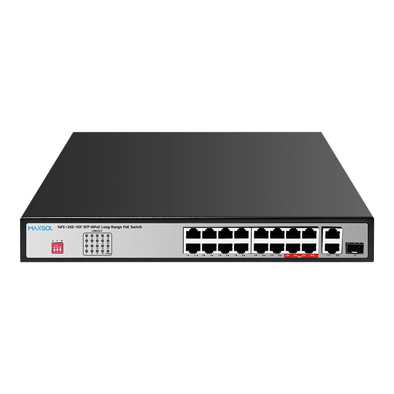
For a larger camera group where Fast Ethernet camera ports meet the traffic design, the PS11602FE 16-port Fast Ethernet PoE switch with Gigabit and SFP uplinks provides 16 Fast Ethernet PoE ports, two Gigabit copper uplinks, one Gigabit SFP uplink and a 200W PoE budget. Its one SFP uplink makes it a candidate for a single fibre return from an aggregation cabinet, subject to the selected module and network design.
Where more camera-facing ports are required at one location, the PS12402FE 24-port Fast Ethernet PoE switch with Gigabit and SFP uplinks provides 24 Fast Ethernet PoE ports, two Gigabit copper uplinks, one Gigabit SFP uplink and a 300W PoE budget. Check the aggregate camera load carefully, particularly where PTZ cameras or cameras with higher peak power requirements are included.
The Fast Ethernet versus Gigabit choice at the camera port should be based on the camera and traffic plan, not simply the camera count. The uplink is shared by all connected cameras, so calculate total expected traffic and allow for operational peaks, additional viewing stations and future cameras.
Fibre deployment checklist
Use this checklist before procurement, installation and commissioning.
Before procurement
- Count cameras at every switch location and reserve ports for reasonable growth.
- Record each camera’s maximum PoE requirement and calculate the combined load per switch.
- Identify the required uplink count at every edge and head-end location.
- Map the network path from cameras to recording and monitoring equipment.
- Confirm whether the topology needs a single uplink, separate network segments or a resilience design.
- Identify the existing or planned fibre type, fibre core count and connector system.
- Select SFP modules only after confirming port speed, fibre type, connector format and required optical budget.
- Check that the head-end switch, media equipment or NVR network has a corresponding compatible fibre connection.
During installation
- Keep fibre and power routes organised and clearly labelled.
- Protect outdoor cable entries, cabinet penetrations and exposed runs against the site environment.
- Maintain correct bend control and avoid crushing or sharply kinking fibre cable.
- Label switch ports, SFP modules, fibre cores, patch-panel ports and remote cabinet locations consistently.
- Apply appropriate earthing and surge-protection practices to powered equipment and copper connections according to the site design.
During commissioning
- Verify that the fibre link establishes at the intended speed.
- Check link status at both ends before investigating camera configuration.
- Confirm camera power draw does not exceed the switch’s total PoE budget.
- Test simultaneous recording and live viewing for the expected camera group.
- Verify VLAN or other network-segmentation settings where used.
- Confirm that every camera is reachable after a switch restart and that watchdog or management features are configured as intended.
- Store the final topology drawing, module details, fibre test information and port schedule with the handover documentation.
A well-planned SFP uplink CCTV network uses fibre where it improves the route and topology, while keeping power, traffic and module selection as separate design checks. Compare the linked Maxsol models against your required port count, camera load, fibre route, uplink design, environment and management requirements before finalising the specification.